I was tired of breathing in solder fumes- especially when soldering lots, and lots of connections for the various multi-rotors I've been working on. I didn't want to pay the $50 or whatever ready made fume extractors have been selling for, so I repurposed a 12v computer fan, 12v wall-wart and a new-work steel duplex box I had laying around.
I tried using some carbon foam filter left over from an old window AC unit, but it restricted the airflow too much. I mostly just wanted to suck the solder fumes down and away from my face when I'm soldering, so even without a filter it works great for this purpose. The computer fan is also very nice- almost totally silent and moves plenty of air.
New-Work Square Steel Box in vise- tracing out zone to cut out with a sharpie
Sharpie marks the circle to cut out of box
Cutting with a metal cutoff saw in the dremel
Finished Rough Cut
Circle Trimmed Out, be sure to file down all the sharp edges!
The Size M DC power jack is for a left-over 12v "wall wart", and a SPST switch to turn it on and off
Box clamped in vice, holes drilled for the power jack and on/off switch
Components trial fit in box
Primed box
Box painted, Components installed & soldered in place
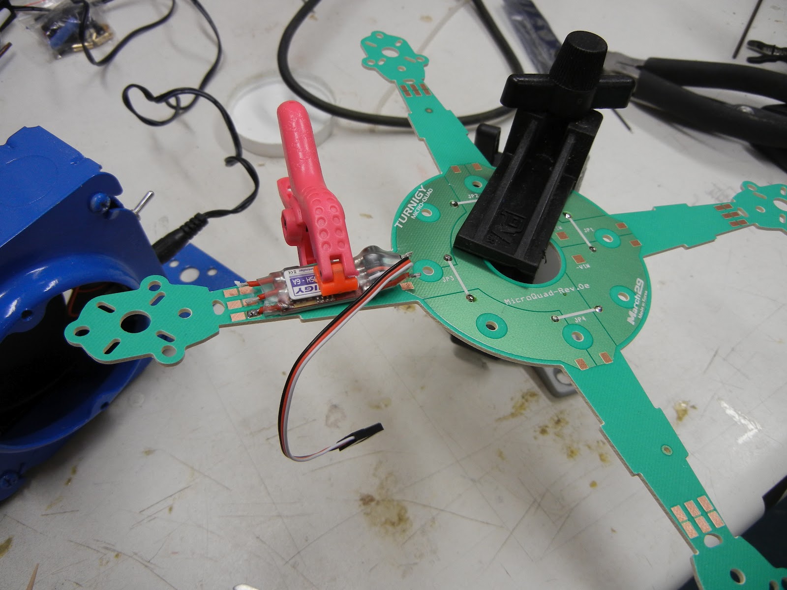
The Turnigy Micro-Quad was a bit of an impulse buy- I saw pictures of it sitting in the palm of someone's hand and couldn't resist. Part of the cool factor is that the structure forms the power distribution board- it has a built-in PCB that you directly solder the ESC's and motors to. Hobbyking was perpetually out of the small brushless motor they recommended, so I chose a Hextronic motor that had similar specs. It turned out to work very well for this application.
I cut the input and output leads down to about 1/8" longer than the heat shrink ESC package and stripped off as much of the insulation as I could. Before clamping the ESC to the quad's frame I dip coated each wire tip in flux.
Micro-Quad frame clamped in PanaVise for easy access.
I used a heat-sink clamp to hold the wires in place during soldering. One down and two to go in this photo.
Once the ESC's were soldered in place I installed the motors. I used 2-56 x 1/4" SHCSs. I used a drop of CA on each 2-56 nut along with some CA kicker to act as a thread locker to prevent the nuts from vibrating off during flight.
Testing motor rotation direction using alligator clips
One slightly more tricky part of this build is that you had to get the motor rotation correct before soldering the motor leads in place, since there are not removable connectors between the motor and ESC. So, I soldered one lead in place, then used alligator clips to test a "guessed" motor hookup. I checked the motor rotation direction by hooking up the receiver and throttling up. If it was correct I soldered the leads in place. If not, just rotate the leads, test again, and solder when correct.
Soldering motor leads in place- note ball of flux on the motor lead wire tip
Once all of the motors and ESCs were soldered into place, I glued together the structure with medium viscosity CA.
Next, I decided to improve the mounting method for the receiver and make room for a Spektrum TM1000 telemetry unit. Telemetry is a great thing to have with an electric aircraft- you can keep an eye on battery voltage to make the best use of your flight time. In order for the TM1000 to transmit your flight pack voltage level, you need to tap the battery somewhere upstream of your ESC's or other electronics. The Hobbyking Quadrotor power distribution board has a nice voltage tap that works great for this purpose. I used a servo lead off of a fried servo for a connector. I pulled off of the signal line to leave just the black and red wires on the servo cable. A JST connector would probably work as well.
quadrotor power board TM1000 voltage tap hookup
To fit the extra TM1000 (and remote receiver) I chose to extend the mounting screws. I couldn't find any 4/40 screws longer than 1.5", so I purchased some 4/40 x 3" threaded rod.
Talon V2 top plate with threaded rod installed
Power Distribution Board and Flight Control Board installed. Note rubber grommets above and below FC board
Receivers and TM1000 velcro'd to plastic cut into squares (from food packaging) ziptied to threaded rods
Top view of Receiver, TM1000 Mounting
Installed on the Talon V2
Mess 'o' wires!
I wasn't happy with the home made aluminum landing gear, switched back to the 600 heli landing gear.
It seems like putting together a simple, functional and light landing gear for a quad copter / multi-copter would be an easy thing. It is, if you want to spend some big dollars and buy a pre-made carbon gear. Personally I'd rather build than buy. Cheaper and more fun.
The first go using some old helicopter skids worked OK, but there wasn't any room for adding a camera for FPV or aerial photography.
First, I tried piecing something together with some 1/2" PVC. It turned out a lot heavier than I had guessed, but seemed to be very durable and the slippery nature of the bottom seemed to make landings easier.
While the PVC flew well, it was just too heavy. If I'd add a camera and FPV camera the Quad could be carrying an extra 1000 grams around.
Next try, aluminum. Home Depot and Lowe's has a great selection of aluminum. One interesting product was a aluminum tile border product- basically an I-beam with cut outs. Seemed to be perfect for some landing gear.
Some plastic golf practice balls made perfect feet.
The aluminum gear turned out to be much lighter than PVC. The aluminum gear plus a Go-Pro and FPV gear should still be lighter than the PVC gear.
The Talon V2 kit for the most part is great. However, it suffers from one annoying design flaw. The landing skids are attached to the motor mounts, so every time you make a less-than-perfect landing, the motor mounts twist on the carbon rods. Once the mounts twist, the motors are no longer aligned and the quad stops flying straight.
So, I removed the stock landing skids and zip-tied on the heli skid set from my old tricopter.
I love my Surly Big Dummy, but I often think about how cool it would be to have a fat tire snowbike also. Banjo Cycles in Madison built a bike that hits both needs with one bike!
Final Hardware Setup
Late last week the APC 10 x 4.7 SF pusher props showed up at the local hobby store, so I was able to finish up the quadcopter and try some first flights. I used a pair of velcro cable tie straps to hold the battery in place.
I marked the "forward" legs of the quad using white electrical tape. Hopefully this will give enough visual definition- if not I'll have to find some colored props.
The instructions that hobbyking includes in their instruction manual isn't the easiest in the world to follow. Luckily Flitetest has a great video to walk you through the process.
Following their instructions, I was easily able to download and install the driver for the Hobbyking KK board programmer. The next step is to download and install the actual software for updating the board's firmware. This is where I ran into a bit of trouble. I tried downloading it several times, and even following Flitetest's instructions to the letter, I could not get the KKmulticopter flash tool software to run. After digging through the flash tool software website's help, I found an explanation about the Java version required to run the software. It turns out if you have a 64 bit flavor of windows (which most is these days), you might need to have both 32 bit AND 64 bit Java installed. By default the 32 bit is installed, but it won't run the flash tool if you have a 64 bit system. So, I downloaded and installed Java 64, and sure enough it worked. After that upgrading the firmware was a snap.
I chose to install Kapteinkuk's 4.7 x-copter software. This also required rewiring each of the motors because the rotation direction changed for each prop. A quick tip I learned is to leave the ESC leads a bit long to allow easy reversal of motor direction.
Before doing anything else, I ran out and tried to fly... I found out immediately that the yaw gyro was reversed- as soon as the landing skids left the ground the entire aircraft started spinning like a top. No good there. So I located the instructions online on gyro reversal, fixed the yaw axis, and also followed the instructions to recalibrate each ESC. After all of that, the update seems to have really helped.
Another note is that zero on the pots seems to be full CCW not CW as discussed on some locations online. Even without spending much time yet tweaking the P and I terms for pitch and roll, and the P term for yaw it is already much, much more stable than the stock firmware and enormously better than my old tricopter.
I'll be posting the terms once I figure out what works best for my setup.
I've copied some basic setup information from KapteinKuk's and other's posts on RCgroup's for easy reference:
Roll pot now controls P-term gain on roll/pitch axis. Pitch pot now controls I-term gain on roll/pitch axis. Yaw pot controls P-term on yaw axis as before. Yaw axis I-term is fixed at 0.2
X-mode setup: Motor 1: front left, CW Motor 2: back left, CCW Motor 3: Front right, CCW Motor 4: Back right, CW
Suggested initial setup:
P pot at 50%
I pot at 0% (it can be left at 0% since it does not have a secondary function.
Yaw P pot at 50%
Trim it level.
Adjust P (roll/pitch) to your liking.
Add I until it flies straight forward without pitching up.
;---- Gyro direction reversing ---- ;---- 1: Set roll gain pot to zero. ;---- 2: Turn on flight controller. ;---- 3: LED flashes 3 times. ;---- 4: Move the stick for the gyro you want to reverse. ;---- 5: LED will blink continually. ;---- 6: Turn off flight controller. ;---- 7: If there is more gyros to be reversed, goto step 2, else set roll gain pot back. If you move the throttle in the step 4 above, you will reverse the pot direction.
;---- ESC Throttle range calibration. This outputs collective input to all motor outputs --- ;---- This mode is entered by turning yaw gain pot to zero and turning on the flight controller. ---