Monday, May 14, 2012

Turnigy Talon V2 Build: Part 2

After the frame was bolted together, motors and ESCs wired up, the next step was to connect the receiver to the Hobbyking multirotor control board. For this, you need male to male servo cables. I didn't have any of these handy, but I did have some male servo connector ends and some servo cables I could cut up.

How to attach Servo Cable Ends
The last time I tried to put on my own connectors I didn't have a proper crimping tool, I just tried crimping the electrical connectors on the wires with a needle nose pliers- to disastrous results. So, I picked up a crimp tool at RadioShack. It isn't quite right, even the smallest notch is slightly too big, but it's really close.

D-Sub Crimping Tool


Servo Cable Cut, Ends stripped ~3mm

Connectors Crimped, Applying flux

Holding Connectors In 3rd Hand Tool, Prior to soldering

Once the connectors are soldered onto the ends of the cable, they simply snap into the molded plastic connector body. Take care to snap each wire into the correct slot in the plastic connector so the ground, VCC, and signal wires correctly map from end to end of the cable.

Finished Cable, 1st one- a little ugly but it works


Initial Setup of the Hobbyking Multi-Rotor control board with a Spektrum DX8 (or DX6i, DX7)
Now that the system is wired up, it was time to fire up the motors and set the rotation direction before the props are attached.

After doing some web research one surprising thing I learned was the radio needs to be in ACRO mode rather than HELI- totally different than a Tri-copter setup.

I connected the receiver, (an AR6110) bound it to the DX8, and attempted to spin up the motors. Nothing. I couldn't get the LED on the multi-rotor control board to light. I followed the instructions off the Hobbyking website, dropped the throttle trim all the way down, moved the throttle stick to the bottom and full right. Still nothing. I tried re-binding the receiver, testing to make sure the receiver was properly bound, etc- still nothing. Finally, I realized that the rudder channel might need reversing. Reversed it, and the control board armed right away. It still needs the throttle trim to be completely bottomed, but now it easily arms by going to minimum throttle and holding the rudder in full right position for a few seconds.

Once the control board would arm, it was easy to check the motor rotation directions and switching two of the motor lead wires for the motors that needed to be reversed.

The pusher props are still on order- as soon as they arrive I'll be able to install all props and finish the setup and try the first flight!

Wednesday, May 9, 2012

Sunday's ride past minnehaha falls


Sunday, May 6, 2012

Turnigy Talon V2 Build: Part 1

The tricopter I built last year has been sitting gathering dust- it never flew well enough for me to have any fun with it. I've been watching the prices on the KK board clones drop in price, and when I noticed that Hobbyking released a new carbon fiber quadcopter frame I had to pull the trigger and give it a try again.

I'm re-using the 18A ESC's, receiver, and some other bits from the Tricopter. Otherwise it's a fresh build.

Component Qty
Turnigy Talon V2 Quadcopter Frame 1
Hobbyking multi-rotor control board v2.1 1
Quad-rotor power distribution board 1
Turnigy L2215J-900 Brushless Motor (200w) 4
Hobbyking SS series 18-20A ESC 4

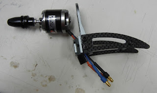
 THe L2215 900kv motors are a bit of an unknown- Hobbyking was out of stock of pretty much everything else. The L2215's fit, but the bolt pattern only allows two screws instead of the normal four to attach them to the arms. Also, it would be better to have a motor that has mounting holes on the side of the motor that shaft protrudes from to allow the motor to be below the mounting arm. You could push the shaft through on these motors, but to do so you need to loosen some tiny allen screws- which when I tried, seemed like they really wanted to strip the heads. So I left well enough alone and mounted them without moving the shafts.
Nice packaging.

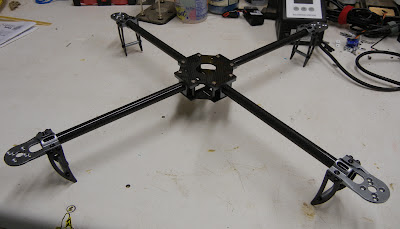
Assembled frame without electronics

Quick review- the frame seems very nicely done. The aluminum bits are nicely machined and anodized, and the quality of the carbon fiber seems good. I did have to drill out a few of the holes on the flat carbon plates which form the center hub of the 'copter.

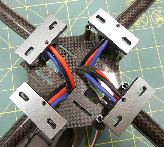
One of the sweet things about this copter design, is that you can run the motor wires through the inside of the carbon arms. To do so, the motor leads need to be long enough- I found that they should be about 10 inches total from the tip of the wire connector to the side of the ESC body. This provides enough length to allow the wires to be loaded through the tube during assembly and plugged into the motor connectors.

In order to add length to the ESC motor leads, you need to join wire extensions to the ESC. I used an overlapping butt joint. I also used 14 gage wire, overkill for this application, but it's what I had available. Going with some 16 or 18 gage wire would save some weight.

Applying flux to end of wire
ESC lead inserted into center of wire
Once the ESC lead is inserted into the wire, I applied head with a soldering iron and wicked solder into the joint. I finished it off with some heat shrink. Again, it's best to slide the heat shrink over the wire before you add the connectors- it makes assembly much easier.


ESC with added cable  length
I re-used the ESCs from my old tricopter, which is why there is multiple wire joints shown in the photo above.

If you are using new ESC's, you'll want to hold off on adding the battery connector to the ESC.


Wires threaded through carbon rod
Motor mount, wires ready to go

All four arms with wires.

The pre-cut holes in the bottom carbon fiber plate are just the right size to allow feeding the ESC and wire harness through. This will allow mounting the ESC's to the edge of the 'copter hub later.

Mess 'o wires
The Turnigy Talon V2 kit came with some nylon posts, nuts, and screws to mount the control board on top of the hub. However, I couldn't figure out how to use that hardware to also mount the Hobbyking power distribution board. The power power is exactly the same size and has the same mounting holes as the control board. The option I'm going to try first is just to use some 4/40 x 1" long screws and appropriate nuts, spacers, and servo grommets.
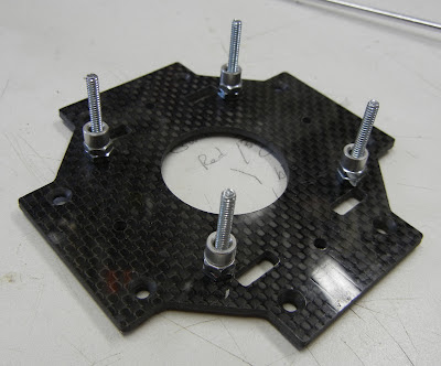
4/40 x 1" screws inserted from the bottom of the carbon plate

After I inserted the screws from the bottom, I fixed them in place with two nuts per screw tightened against themselves. I then used some aluminum spacers to give enough room between the carbon plate and the power board. I think these spacers were landing gear wheel spacers from my defunct Parkzone T-28. Always part out those crashed planes and keep the misc. hardware!

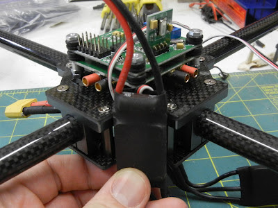
Power distribution board installed
After the power distribution board is in place, the rubber servo grommets can be placed on the screws. The grommets will provide some vibration damping for the control board. Less vibration = more accurate control and less error from the piezo gyros.


Control board stacked
The 1" 4/40 screws are just long enough to put another set of grommets on top of the control board and fasten everything down with a single 4/40 nut. I might try re-doing the stack with a shorter spacer on the bottom, to allow a double-nut or locknut to be used on top. I'm worried the nuts might loosen or fall off in flight, causing a big problem. 

Stacked boards- side view

Test Assembly

Zoom view of the stack
Now the trick- how to wrangle all of the ESC's, power cables, and ESC control  cables into something resembling order. It looks like the ESCs could be zip-tied to the corners of the hub. Two possible orientations present themselves- horizontal:


Horizontal

Vertical
Vertical made more sense to me- it seemed to allow for better fit of the various wires. 

Since my ESC's already had EC3 battery connectors soldered on, I had to make some short adapter harnesses. The Hobbyking power distribution board had 3.5mm female sockets soldered on. If I was using brand new ESC's I would have simply soldered 3.5mm male connectors onto the ESC's and directly plugged them into the board. That would have made for a neater and lighter installation. Also, fewer connectors = less possible failed joints. If I really like how this flies I might clean things up a bit. I'd also replace all of the 14 gage wire with lighter 16 or 18 gage.
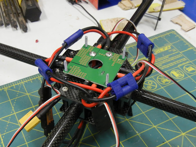
ESC's all plugged in.

 Next steps:
  1. building battery mount
  2. hooking up control board
  3. prop & motor setup
  4. Fly!
 Once it's proven to fly, I'm hoping to use this for a number of things:
  • airborne photography
  • FPV? 
  • stringing Christmas lights in tall trees?

Parkzone Icon A5 tail fix

A week ago I had a very hard crash with my Parkzone Icon A5 after a radio glitch (or elevator servo problem?) caused the airplane to dive at high speed into the lake.

The fuselage glue together nicely with white Gorilla glue. The tail, on the other hand, was a problem. The foam was crushed in one area making it really difficult to glue it back together straight. I decided to insert a small carbon fiber reinforcement to keep it straight.

Carbon strip recycled from a RIP aircraft

Sizing it up

I chose to insert the carbon in the natural joint between the vertical stabilizer and the fuselage foam pieces. I had to use an X-acto knife to lengthen and deepen the slot to make room for the carbon strip.

I manually held the tail as straight as possible, inserted the carbon strip, then wicked in some foam-safe thin CA. Once the strip was tacked into place, I filled the slot with some thick foam-safe CA and used some accelerator to cure it.

Finished product
I haven't yet flown it.... I'm crossing my fingers that everything is straight and true!

Spektrum TM1000 telemetry voltage probe installation

I recently upgraded from a Spektrum DX6i to a DX8. Among the new features is telemetry- and the new radio came with a TM1000 telemetry module, a temperature probe, and a voltage probe. For me, the main advantage is to be able to set a low voltage alarm so you can fly out the entire flight pack. This is really helpful when you might be using a range of battery capacities- on my Parkzone Icon A5 I use everything from a 1300 mAh to a 2200 mAh, which makes using a simple timer useless.

The temperature probe doesn't need any real installation- just plug it in and attach the sensor to whatever you want to measure, so very quick and easy. The voltage probe does need to be hard wired into the aircraft's electrical system. I decided to make a removable wiring harness so I could easily move the TM1000 and voltage probe from aircraft to aircraft.

Making a custom harness is very easy for anyone who is capable of soldering their own EC3 connectors.

Voltage Probe, as from Spektrum

Step 1: Cutting the wires

Wires, cut to length
I used Turnigy 14 gage wire. Choose your wire according to expected current draw. I cut the wires to 2" in length. Shorter is probably better for fitting in your airplane, but it gets more difficult to solder and attach the connectors. If I were to do it again, I might try 1" pieces.


 Step 2: Trim the insulation


Roll cutting
I like using a roll cutting technique. Use a razor blade or X-acto knife and gently press into the wire insulation while rolling the wire. Take care not to press too hard or you'll cut through wire strands. You could also use a wire stripper, but for small trims like this I find the roll cutting technique to be easier and more convenient. For these connectors I chose to remove 1/8" of insulation from each end of the wires.


Insulation trimmed

Step 3: Soldering the connectors

Set up in 3rd Hand Tool
You'll have to choose which end of the wiring harness you want your sensing wires to go. It doesn't matter if it's the battery end or the ESC end. Just take care to make sure your polarities are all correct, if they aren't you can easily fry your ESC, TM1000, battery, etc.
 
A third hand tool really comes in handy here. It's a bit tricky to solder both the power wire and the sensing wire into the connector at the same time. In the photo above you can see both wires inserted into the connector before soldering. I like to hold the soldering iron on the outside of the connector, wait for everything to get hot enough, then feed the solder into the joint. It also helps to put a bit of soldering flux on the wire tips.

Finished connector
  Once the connector is soldered, press it into the EC3 plastic body. There are plenty of online videos / guides elsewhere to show how to do this in detail. Repeat for both wires.

Harness with one end complete
Before I attached the connector to the other end, I chose to put a bit of heat shrink to act as a strain relief.

Completed harness, ready for installation