Sunday, September 17, 2017

Arduino controlled 3D Printed Automatic Fish Feeder

Recently I designed & put together a really simple small aquarium automatic fish feeder. The design files & simple build instructions are located on Thingiverse here.


And, since I didn't immediately see an easy way to park code on Thingiverse, the code is below:

/***********************************************************************************
Small fish feeder

code is set to have the feeder run 1x per day. It runs once immediatley upon startup,
then waits 24 hours for next run. For testing comment out the DAY (24*HOUR) line
and uncomment Day (2*SECOND) line
*****************************************************************************************/

#define SECOND 1000L
#define MINUTE (60*SECOND)
#define HOUR (60*MINUTE)
#define DAY (24*HOUR) //uncomment for actual run
//#define DAY (2*SECOND) //test setup

const int SERVO_PIN = 3; //pin number for the led pin - this is 'const' since it will not change during code, and saves Arduino memory
const int FILL_DEGREE=5; //starting hole location, fill slider with fish food
const int DISPENSE_DEGREE=45; //dispensing hole location

Servo servo1;

//setup runs once when the Arduino is turned on
void setup()
{
servo1.attach(SERVO_PIN); //attach the servo on pin SERVO_PIN

} //setup() is done, go to loop()

//loop runs forever once setup is complete
void loop()
{
//******************************************************************************
//NOTE: YOU WILL HAVE TO CHANGE THESE VALUES based on your servo horn alignment.
//******************************************************************************

servo1.write(FILL_DEGREE); // tell servo to go to fill position
delay(1000); // delay for 1 second
servo1.write(DISPENSE_DEGREE); // tell servo to go to dispense location
delay(1000);
servo1.write(FILL_DEGREE); // tell servo to go back to fill position

delay(DAY); // delay for 1 day
}

Tuesday, May 23, 2017

Fixing battery powered air mattress inflator with an Arduino Nano & Lipo batteries

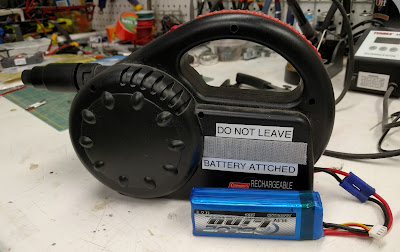
Our rarely used air mattress inflator bit the dust. It's a old Coleman rechargable Quickpump that used a 6 volt lead acid battery. It had two problems. One, the battery was toast and wouldn't accept a charge, even when directly attached to a nice charger. Two, I had lost the charger some time back so even buying a new battery would cause a charging hassle. Instead of buying a plug-in charger which would have been the easier move, I decided to fix it using parts on hand.

Be warned that any dealing with LIPO batteries is potentially risky. Try this at your own risk!

Proposed solution:

  • 2s or 3s LIPO batteries- normally used for drone or RC airplanes. Great power source but a bit risky to use since they do not have any built-in over discharge protection.
  • MOSFET to handle power distribution
  • Arduino Nano- I thought it would be possible to use the Nano to control the system and safely run the pump off of the LIPO using the following strategy:
    • using a voltage divider, read the battery voltage and determine if it was a 2s or 3s battery (assuming the use of a LIPO pack)
    • determine if the battery is in a safe operating voltage, and if not, shut the system down
    • PWM the output to simulate a 6V power source for the motor
It's not well tested, and the code is messy, but it seems to work fine. I ended up not using the indicator lights as listed in the schematic and code. They really were not necessary, and they also seemed to make the circuit not work- perhaps I didn't have the pull down resistor sized properly on the MOSFET gate?
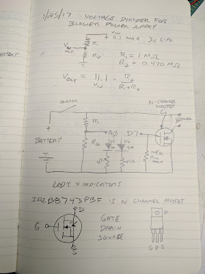
Schematic with calculation for voltage divider

There is a specific MOSFET listed, but any MOSFET that is N channel and can handle sufficient current should work. 

I tested the circuit out on a breadboard first. After that seemed to work I soldered it on to a cheap 4x6cm protoboard and installed it in the pump shell. It was a bit of a tight fit on the protoboard. 
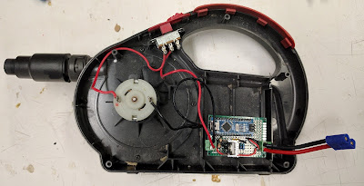
Circuit installed in pump shell
The way it actually is wired is with the off/on switch controlling the + output- this way the Arduino will boot as soon as the battery is connected. The downside is that the Arduino will draw power the entire time the battery is connected- which would eventually destroy the LIPO.

Circuit detail

ready to rumble!


Ugly code- note there is a collection of serial print hooks to track what is going on with the code / circuit:

/*
This software allows a 3s or 2s LIPO to power a 6V air mattress inflator

reads input voltage through voltage divider
determines if 2s or 3s battery is attached
if battery is in acceptable voltage range, allows pump to run and turns green LED on
if battery is too low, does not allow pump to run and turns red LED on

utilizes analog output (PWM) to simulate desired output voltage using MOSFET to control higher voltage and current from LIPO battery
 */


void setup() {
  // initialize serial communications at 9600 bps:
  Serial.begin(9600);
}

void loop() {
// constants

int analogInPin = 0;  // Analog input pin that the potentiometer is attached to
int GreenLEDPin = 5; // digital output pin that the green LED is attached to
int RedLEDPin=6; // digital output pin that the red LED is attached to
int MOSFETPin=3; //output pin for MOSFET, must be PWM capable pin
float R1=100; //R1 value of voltage divider (divided by 1000)
float R2=48; //R2 value of voltage divider (divided by 1000)
int Lipocell=0; // default lipo cell count
float mincellV=3.0; //standard low lipo cell voltage
float cell_cutoffV=3.2; // cutoff voltage
float maxcellV=4.2; //standard high lipo cell voltage
float batteryV=0; //battery voltage
float sensorValue=0; 
float inputVoltage=0;
int outputV=6; //voltage desired for output
float outputValue; //value for analog output

//pinMode(MOSFETPin, OUTPUT); //set MOSFETPin as output

  // read the analog in value:
sensorValue = analogRead(analogInPin);

inputVoltage=sensorValue * 0.0049; // 5 volts / 1024 resolution = 0.0049

batteryV=inputVoltage * (R1+R2) / R2 ;

// determine if battery is 2 cell or 3 cell battery or if no battery is connected
if(batteryV >= (mincellV*2) && batteryV <= (maxcellV*2)) Lipocell=2; //set cell count to 2
if(batteryV >= (mincellV*3) && batteryV <= (maxcellV*3)) Lipocell=3; //set cell count to 3
if(batteryV < (mincellV*2) ) Lipocell=0; //set cell count to 0 (no battery)

outputValue = map(outputV, 0, batteryV, 0, 255); // map desired output voltage to PWM & output

// determine if the battery voltage is within acceptable range and battery is present & act accordingly
if(batteryV > (Lipocell * cell_cutoffV) && Lipocell != 0) 
{
  analogWrite(MOSFETPin, outputValue); //start MOSFET using PWM value
  Serial.println("turning on output pin");
  digitalWrite(GreenLEDPin, HIGH); //green light on
  digitalWrite(RedLEDPin, LOW); //red light off
}
else
{
  analogWrite(MOSFETPin, 0); // if battery too low set output to zero
  Serial.println("turning off output pin");
  digitalWrite(GreenLEDPin, LOW); //green light off
  digitalWrite(RedLEDPin, HIGH); //red light on
}

  // print the results to the serial monitor:
  Serial.print("input voltage = ");
  Serial.println(inputVoltage);
  
  Serial.print("battery voltage = ");
  Serial.println(batteryV);

  Serial.print("LIPO cell count = ");
  Serial.println(Lipocell);

  Serial.print("output value=");
  Serial.println(outputValue);

  Serial.println(); //blank line for clarity

  // wait XX milliseconds before the next loop
  
  delay(1000);
}


Sunday, January 8, 2017

Shapeoko2 X-axis beam upgrade & Dinosaur Bookends

The stock Shapeoko2 used two standard makerslide extrusions, separated by a small air gap, for the X-axis linear rail. This worked OK, but the assembly tended to twist and cause inaccuracy or cutting problems when driving the machine too hard. Some people stiffened their machines by bolting the two extrusions together or otherwise tying the two beams together and approximating a single beam.

Inventables recently released a new "Wide Makerslide" for their X-Carve CNC router. This new extrusion replaces both X-axis makerslides in their X-Carve product, and yields a much stiffer X-axis. This new part is a very easy and fast upgrade for older Shapeoko2 machines. They sell it in 500mm, 750mm, and 1000mm to fit most machines. My machine has the narrow X-axis so I needed the 500mm part.

Stock setup on the left, still assembled. New extrusion on the right.
Pay close attention to stepper motor wiring order when disconnecting Y axis steppers to disassemble unit
Together and ready for testing!
Cutting out parts for Dinosaur Bookend for Christmas present
The first project built with the upgraded Shapeoko2 were a set of these cool dinosaur bookends. They turned out great and were a hit at Christmas. The ~0.5" plywood was sourced from Menards- they had a super sale on Christmas Tree bases- pretty nice quality pseudo baltic birch 2' x 2' squares for $1.90. The bookend bases were cut from Ikea bamboo cutting boards.

Finished bookends

Shapeoko 2 Upgrades using XCarve parts

This post is actually a little out of order- I actually did this before rebuilding the Z-axis.

After doing some initial aluminum cutting and also running into some size limitations with the stock Shapeoko2, I decided I need to upgrade the machine to make it both a) larger and b) stiffer.

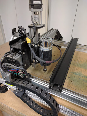
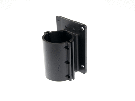
Inventable's X-Carve has a number of parts that are bolt-on upgrades that are compatible with the Shapeoko 2. The first I purchased was the improved DC Spindle mount. This provided a much-improved interface between the DC spindle and the Z-axis slide- both improved rigidity and alignment. It's machined from a single aluminum extrusion and black anodized.
Spindle Carriage
DC Spindle Mount
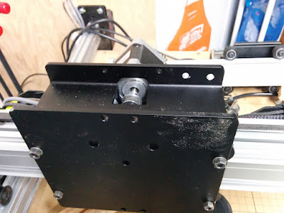
The second upgrade I purchased was the X-Carriage Extrusion. This was definitely a huge upgrade over the stock Shapeoko2 X-Carriage. The stock x-carriage is an assembly of plates bolted together with a ton of spacers and washers- it works, but the improved part is one massive extrusion. It should prove to be much stiffer in actual use.
X Carriage Extrusion
X-Carriage Extrusion


Installation of the upgrades was pretty straightforward. The entire Shapeoko2 X axis needs to be disassembled. The wheels and stepper motor can be attached to the X-Carriage. Then, the X-carriage extrusion is slid over the X-axis Makerslide extrusions. 
X-Carriage assembly in process.
Once the X-axis is re-assembled, the Z-axis with the new, improved DC Spindle mount can be bolted on and everything aligned.

I also took the opportunity to expand the stock build surface using new makerslide and some 8020 extrusions I purchased from an industrial salvage place.
Installing electrics on a board attached to the bottom of the frame

New, Super Beefy 8020 Frame, laid out but not yet squared
Just about ready to bolt together
Squared up and bolted together.

I used the stock 500mm x 500mm wasteboard, then added a new wasteboard I cut from 1/2" MDF. I did buy a set of 5mm threaded inserts to add hold downs to the new section.

New wasteboard cut from 1/2" MDF and hole locations marked
Holes cut and M5 threaded inserts added
New Wasteboard & Y axis makerslide braces in place
Assembled and ready for first part- a new faceplate from 1/8" MDF:

Cutting faceplate for E-stop and spindle RPM control
Faceplate cut & spray painted silver
Finished, assembled and ready to go


Shapeoko 2 Z-Axis upgrade to ACME screw thread

After having my Shapeoko 2 for a few years, I decided it was time to give the Z-axis an upgrade to the ACME screw threaded rod, vs. the standard threaded rod it came with. This upgrade should improve Z-axis precision and speed, as well as clean up the mechanical "look" of the system.

I used parts from Inventables- I've always found them to be high quality with good service and speed.

www.inventables.com components used: (with P/N)
  • ACME Lead Screw Kit 30658-01 (includes M6 locknut)
  • Z-axis motor plate 30534-01
  • GT2 Belting 2" x 3" x 1/4" 30547-01
  • 20T GT2 Pulley, 8mm Bore 26054-04
  • 20T GT2 Pulley, 5mm Bore 26054-01
Additional hardware used:
  • 2x M5 x 8mm button head screws
  • 1x M3 x 12mm socket head cap screw (SHCS)
  • 1x M3 washer
Inventables has a great step-by-step illustrated set of instructions for the newer X-Carve CNC. Their instructions are mostly appropriate for upgrading their older Shapeoko 2 as well. 

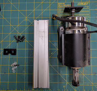
Before I could start assembling the new Z-axis, I had to take apart the existing, stock Shapeoko2, Z-axis.
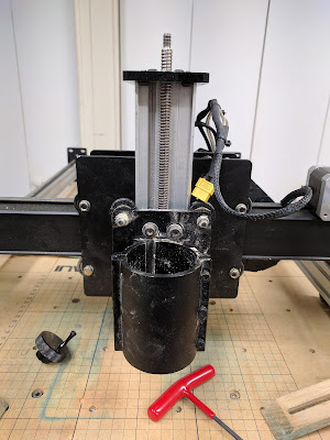
Stock ShapeOko 2 Z Axis - before disassembly
Z-axis apart and on the table

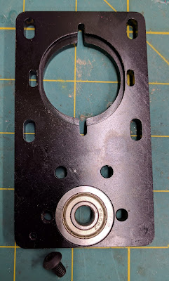
1) Use 2x M5 x 8mm button head screws (new screws to assembly) to retain the stock thrust bearing in the new Z-axis plate. I didn't have M5 x 8mm button head screws in my hardware collection, so I used the screws from the belt clips on the Shapeoko and used some M5 x 8mm SHCS on the belt clips.

Thrust bearing in Z-axis plate

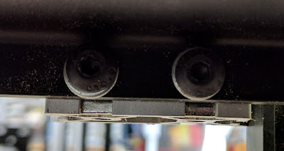
Screws in place to retain the bearing

2) Use 2x M5 x 20mm button head screws to attach the Z-axis plate to the Z-axis makerslide. These screws were part of the original Z-axis assembly. I left the screws a little loose to allow for adjustment once everything was assembled.


3) Attach Z-axis makerslide to X-axis rail using original hardware. At this point it pays to take some time to get the Z-axis makerslide as square as possible with the rest of the machine. The recommended  height is to leave just enough makerslide exposed below the X-axis slide to not expose any of the T-slot clips. Depending upon how you want to complete your assembly, you might also consider loading the Z-axis plate to the Z-axis makerslide before bolting it onto the machine.
Squaring Z-axis slide with the machine
Adjusted height to not expose the T-slot clips. 

4) Took off Z-axis plate assembly, dropped Z-axis slide with ACME screw and block onto makerslide, then re-attached Z-axis plate assembly
Z-axis slide attached

5) Attach 20T GT2 Pulley (8mm bore) to top of ACME screw with setscrews, then tighten down M6 locknut)
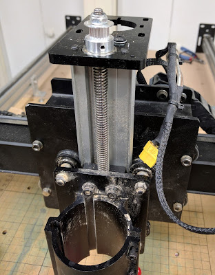
ACME Screw 20T GT2 Pulley and locknut installed

6) Using 3x existing M3 x 12 SHCS & M3 washers, plus a new M3 x 12 SHCS & washer, attach stepper motor to Z-axis plate. Do not tighten screws though- you'll need the slop soon to tighten the belt.

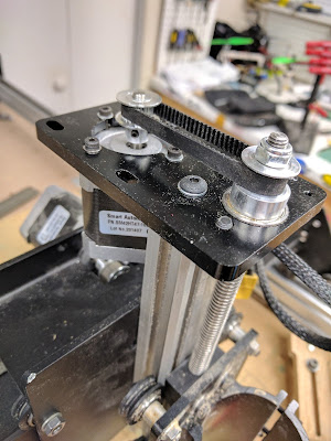
Z-Axis motor installed

7) Attach the second GT2 pulley to the stepper motor shaft. 

8) Load the GT2 Belt across the pulleys. You might have to loosen and remove the motor to get the belt in place. I actually had to completely detach the stepper motor to get the belt across the pulleys. 
Belt in place, ready to test
9) check that everything is square and all screws are tight.

10) Use Universal G-Code sender or another G-code sender to update the Z-axis steps per mm:

Update Z-Axis setting to:
188.976 Steps/mm (for 12 threads per inch ACME screw thread)

with the following command in Universal G-Code Sender: $2=188.976


Enter $$ in the Universal G-Code sender command prompt to get a list of current GRBL settings. Take a look at the $6 setting- I had to subtract 128 from my current $6 value.

After getting everything set up, it was time to test by manually driving the tool head around using the Universal G-Code Sender's manual controls. Initially I had some binding and stepper motor skipping steps. I ended up having to do a few things to fix the step skipping:
  • loosened the screws attaching the Z-axis plate to the Z-axis makerslide, re-aligned the parts
  • added a little silicone grease to the ACME screw
  • increased the current to the Z-axis stepper by 1 increment on the adjustment pot
No test parts yet....