The next step of my RepRap MendelMax 1.5 build was to construct the Y-axis carriage. I didn't purchase any of the pre-made Y-axis bearing plates. Since I had plenty of the Bosch aluminum extrusion left from my frame build, I built the Y-axis carriage from the scraps. I chose to make the Y-axis carriage 8" per side. This will give about 1/4" of overhang for the heated build platform.
Frame built & screwed together using 90 degree brackets
T-Slot nuts installed for Pillow Blocks (8x T-slot nuts) and Belt Clamps (4x T-Slot nuts) I put a piece of painter's tape over the end of each extrusion to prevent the T-Slot nuts from falling out when I was installing the Y-axis carriage.
Y-Carriage installed in Mendel Max 1.5 frame- showing detail of belt clamps and 8mm bushing pillow blocks
Y-Axis Carriage Installed!
Now the mechanical assembly is basically finished. I still have to install the extruder, hot end, and (3x) endstops.
The RAMPs 1.4 controller board, Arduino, and power supply also arrived at my doorstep last week. I'm a bit unsure of the installation, wiring, and setup of the electronics. It seems like most people on the web who are building these printers come from the software / electronics side of the world- so their tutorials are almost always fairly in depth for the mechanical assembly but gloss over the electrical side. I have completed a few arduino based electronics projects so I'm sure I'll be able to fumble through it.
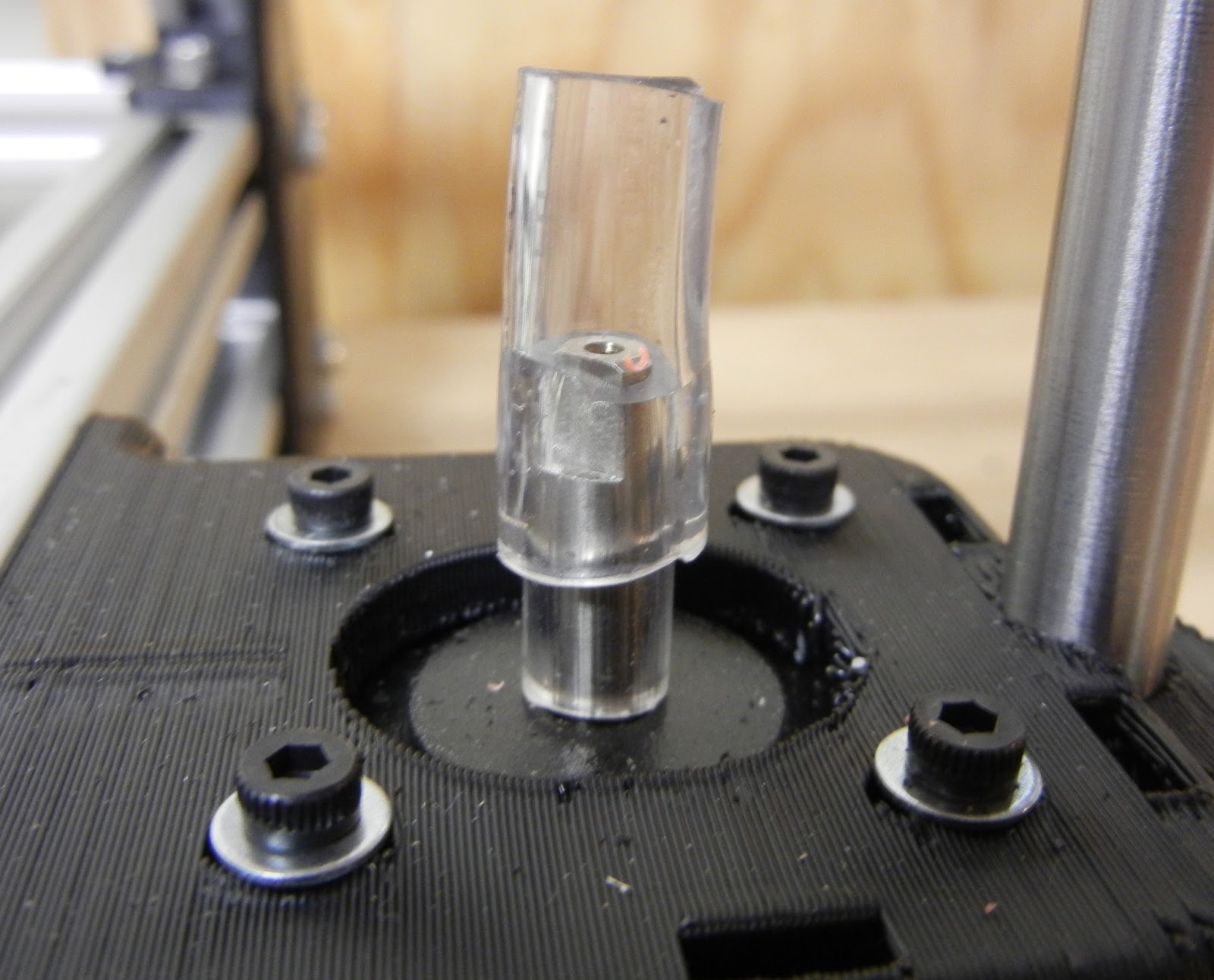
Tonight's activity was to build the flex couplers to link the Z-axis steppers with the acme threaded rod. Rather than purchase a machined flex coupler, or to use a printed coupler, lulzbot.com recommended using a home-made coupler. They recommended using a 5/16" OD x 3/16" ID tube and a 7/16" OD x 5/16" ID tube along with small pipe clamps.
Large Tubing
Small Tubing
Tubes cut to length
Initially I tried a 1.5" long large tube and 0.75" long small tube. I wasn't able to fully insert the small tube into the large tube, so I changed to 0.75" length for both tubes.
The ACME lead screws and nuts showed up, along with the promised replacement parts from www.lulzbot.com.
Next steps in the rep rap Mendel Max 1.5 build- assemble the X-axis ends. I ordered the lulzbot ACME Pillow Block X-End Set 2.0. The Z-axis rods are 10mm, and the X-axis rods are 8mm.
ACME nut in the bottom half of one of the X-ends
The ACME nut didn't quite fit- trimming the socket with a X-acto knife
Perfect Fit!
Lulzbot.com was out of the extruder components, so I decided to order some from an e-bay seller. I found a seller located in Hutchenson, MN
who was selling parts at a very reasonable price. I also purchased some
printed endstop switch brackets, "pillow blocks", and belt clamps as
well.
Additional Parts from E-Bay seller
The SDP bushings for the 8mm and 10mm rods both have the same OD, so the printed "pillow blocks" are the same for all size bushings. The printed "pillow blocks" were a bit rough on the inside, and the SDP bushings didn't fit with a reasonable amount of force. I learned my lesson on the X-carriage not to force the bushings. A round file worked great to clean out the inside of the "Pillow Block". With a little filing, the bushings pressed in place easily.
Filing Pillow Blocks
Pushing Pressed into Pillow Block
Assembled X-Axis assembly
X-Assembly in place
X-Axis in place with frame assembled
With the X-axis assembly in place, I could start dialing in the mechanism. Unfortunately the Z-axis (vertical) wouldn't slide at all, it would easily lock up. Obviously something wasn't aligned right.
The right side of the Z-axis slide seemed to be tighter than the left. I removed one of the pillow blocks, and the assembly seemed to slide slightly easier.
One Pillow Block Removed
After inspection, it seemed the upper pillow block wasn't aligned fore and aft with the Z-axis slide.
Adjusting Mounting hole with dremel.
Even after re-assembly the Z-axis still didn't slide right. After looking at the X-ends further, I saw that there were actually two additional Pillow Block mounting holes on the lower X-end.
See lower mounting holes on lower X-end
Pillow Block moved to lower X-end holes
The X-assembly slid much better up and down the Z-axis after moving the Pillow Blocks.
Lulzbot.com also sent the replacement lower vertices to replace the missing units from the original kit.
Replacement kit from Lulzbot.com
When I re-assembled the frame, I also took the opportunity to replace the upper cross braces with some heavy duty 8020 aluminum brackets from D&S Machined Products. The aluminum braces really stiffened up the assembly. As is, both the X and Z axis easily slide without binding.
After Christmas I had some time available to do some snow bike riding. Sophie the dog loves the snow bike rides on the lake- tons of great running for her:
Perfect day for a ride out on Mooney Lake
Post Ride Bike Pose
A few days later, I was able to sneak out to Elm Creek and ride the off road trails. The beginner trail was tough- very rough and tough to stay down the center. The intermediate trail, on the other hand, was in perfect shape- nicely packed down and very ride-able.
Elm Creek Intermediate Loop
Baker Park, Winter Bike Loop
The Baker Park loop was interesting. There is no off road trails open during the summer in Baker, so being able to ride there in the winter is a nice bonus. The winter trail is just a track that is groomed for skate skiing- so it is wide and fairly hard packed. It's fast, and hilly enough to keep your attention. I'll definitely be coming back, and I'll have to try it after work in the dark.
As a part of my job, I've used many "3D printing" services over the years to construct medical device prototypes- SLA, Polyjet, rapid CNC, etc. I've always thought they would be far too expensive to use for home projects and hobbies. A few weeks ago I was doing some research on in-office prototyping equipment and discovered that hobbyist-level equipment had come way down in price, and there were tons of options for cobbling one together using open-source software and hardware.
Having the ability to make just about any plastic part in your house sounded great. Replacement parts for anything in the home, broken or lost parts to kid's toys, designing new bike accessories, model airplane parts, whatever. Even doing some "lost-wax" style aluminum casting would be fun to do. Plus, there is an enormous amount of free 3D models available online for download and printing at Thingiverse among other places. It might even be useful for manufacturing items to sell on ebay.
RepRap is one of the main open source systems out there, and after doing some research, I decided to build a variant called MendelMax 1.5. The idea behind RepRap is that each completed printer can replicate itself by printing components for another printer. MendelMax was attractive because it used industrial aluminum extrusions to build the frame, there is a local industrial salvage company called D&S machined products that has a large inventory for very reasonable prices.
But, as I found out, a MendelMax 1.5 isn't a uniform species. Everyone has their own tweaks. So, when you order a kit of printed parts from someone, pay very careful attention to exact what hardware you need- it isn't the same from kit to kit. I'm sure it'll change eventually, but right now building a 3D printer is definitely for someone who wants to get their hands dirty and dive into all the details- it's not a plug and play deal.
Since I don't know anyone with a printer, I had to buy the parts. I ordered my kit from Lulzbot.com. They have a polished website, and their customer service was quick to answer questions via e-mail before the purchase. However, their site is a little confusing with many broken links and not a clear BOM to tell you what you need for the 1.5 build. In particular, the kit doesn't include the X-axis parts, and the components to finish the Y axis. If I were to build another with purchased components, I'd probably buy a more complete printed part kit from another source.
I ordered the hardware from McMastercarr.com- lots and lots of metric SHCS, drill rod for ways, etc. Once the build is complete I'll post a complete BOM with sources. I haven't yet decided on which electronic package to use and where to source it.
On to the hardware build:
I purchased some used Bosch 20mm extrusions from D&S. They were in great shape, just a few un-needed holes here and there. I was able to cut them to length using my power miter saw with a standard fine tooth carbide blade. I did clamp the extrusion to the saw and made the cut very slowly. The cut quality turned out almost perfect- I didn't have to do any cleanup filing at all. One of the biggest problems was just finding a metric tape measure- all the majors didn't carry one- Menards, Home Depot, Lowes all lacked a metric tape. Then I remembered that QBP gave away a free tape measure during one of their open houses years ago. I dug it out of my bike toolbox and it worked great.
Cut Quality Illustration
300mm and 420mm Extrusions for printer base
I used the Trinity Labs manual as a guide for assembling the frame. One big difference between their build and the Lulzbot 1.5 design is that Trinity 1.5 uses a linear slide for the Y axis, and the Lulzbot uses two 8mm diameter precision drill rods for the ways. I had to dis-assemble the base so I could insert some additional T-slot nuts to accomidate the Y-axis rod mounts.
Note that all of the black plastic parts seen in the photos are 3D printed ABS parts purchased from Lulzbot.com.
Assembled MendelMax 1.5 base with Rod mounts in place
Y Axis Rod Mount detail
Rod Clamps in place
Since the clamps (like all the plastic parts) were 3D printed, curved surfaces are stepped and are not totally precise. I assembled the rod clamps then drilled them out to clean up the surfaces so they would properly clamp on the 8mm rod.
Cleaning up Clamp to fit 8mm Drill Rod (don't worry, the skewed angle of the drill is only because I was also holding a camera, it was square when I actually drilled the hole)
Test Fit of the 8mm Drill Rod
Cutting the drill rod to length using a hack-saw, vise, and plenty of oil
The Lulzbot MendelMax 1.5 kit didn't include the Y-axis busing holders, so at least for now I'll have to build the frame without the build platform in place.
Ways in place, with 8mm SDP bushings mounted
The build platform moves front to back on the Y-axis slides. It's driven by a stepper motor through a GT2 timing belt. The motor mounts on the "back" of the device base, and the belt tensioner / idler mounts on the "front" of the base. I don't yet have the bearings for the idler. Those will be added later.
Y-Axis Idler / Tensioner mounted
The screw on the top presses against the base extrusions to add tension to the belt
Next step after the base was built was to add the upper platform. Yet another Lulzbot annoyance- I found out the they had included 4x of the Lower Vertex (left) mounts, instead of 2x Left and 2x Right. I assembled the platform anyway just so I could get as much assembly done as possible. The Lower Vertex mounts connect the diagonal beams with the base platform. You can see the incorrect part being used on the lower right hand side of the photo- with the "left" component being using on the "right" side.
UPDATE: Lightning fast customer support from Lulzbot- they said they'd ship out the replacement parts today as well as fix the broken links on their 1.5 kit web page.
Assembled Frame, back view
Assembled Frame, Front View
I did order the X-axis set from Lulzbot. I was only able to press the bushings into the X-slide before I ran out of fasteners and hardware. I didn't clean out the holes quite well enough- in the process of pressing in the bushings I managed to crack one of the bushing sockets. I think I'll be able to epoxy it together. Once the printer is up and running I can simply print a new replacement part.
Pressing 8mm Bushings into X-Axis Slide Using Vise
I ordered the ACME lead screws (for the Z-axis) and many fasteners from McMaster. I also need the bushing holders for the Y and Z axis before I can continue.