Tuesday, April 30, 2013

0.25mm Nozzle, Cartridge Bearings, and Pluto.

I purchased a new nozzle for the printer in an attempt to get higher resolution parts. My original nozzle was a Lulzbot Budaschnozzle 1.3, 0.5mm diameter, which I don't know if they even sell as a stand-alone part anymore. It worked fine, but seemed to make a mess of smaller parts and liked to ooze a lot. I thought I'd go the other direction and went to the smallest nozzle Lulzbot.com sold- a 0.25mm.

While I was on the lulzbot site I noticed they really upgraded their hot end- their new 2.0 version looks really nice- a machined stainless steel backer plate and aluminum heatsink. Much more industrial looking than the older version I purchased only a few months ago.

Since the new 0.25mm diameter nozzle only puts out 1/4 as much plastic per pass as my original 0.5mm nozzle, build times are longer, but the smaller output filament produces a much finer quality part. It also seems to ooze much less when heating and traversing than the original 0.5mm nozzle. I've heard clogs can be an issue with smaller nozzles but I haven't seen that yet. The new nozzle was a snap to install. I was worried about all of the solidified plastic on the inside of the old nozzle making it impossible to remove, but it came off without any trouble.

As long as I was trying to further improve print quality, I thought I'd further reduce free play in the Z-axis 3/8" ACME threaded rods. The bottom is relatively fixed by the stepper motors and the flex couplers. The X-ends attach to the rod via two large brass ACME nuts, but those nuts have some side-to-side free play. During Z traverses the top of the rods can and do trace out an orbit. This must have some effect on Z-axis precision. It's probably very minor, but why not try to reduce it as much as possible. I was able to find some nice cartridge bearings with the correct ID at D&S Machined Products for $2.50 each. NTN R6ZZ/LO14QC. These fit very nicely over the 3/8" threaded rod.


I was planning on designing and printing a slick bearing retainer, but then my father-in-law suggested I simply hot glue them in place. How can you argue with that? Quick, easy, and it'll supply a tiny amount of flex to prevent binding.

Right Side upper Z-axis bearing hot glued in place


For a test of these two improvements, I printed a few copies of the "Pluto" dog off thingiverse. It's a nice size, has smooth compound curves, and some really tough overhangs for the ears and mouth. In short, a good test for trying to improve print quality.
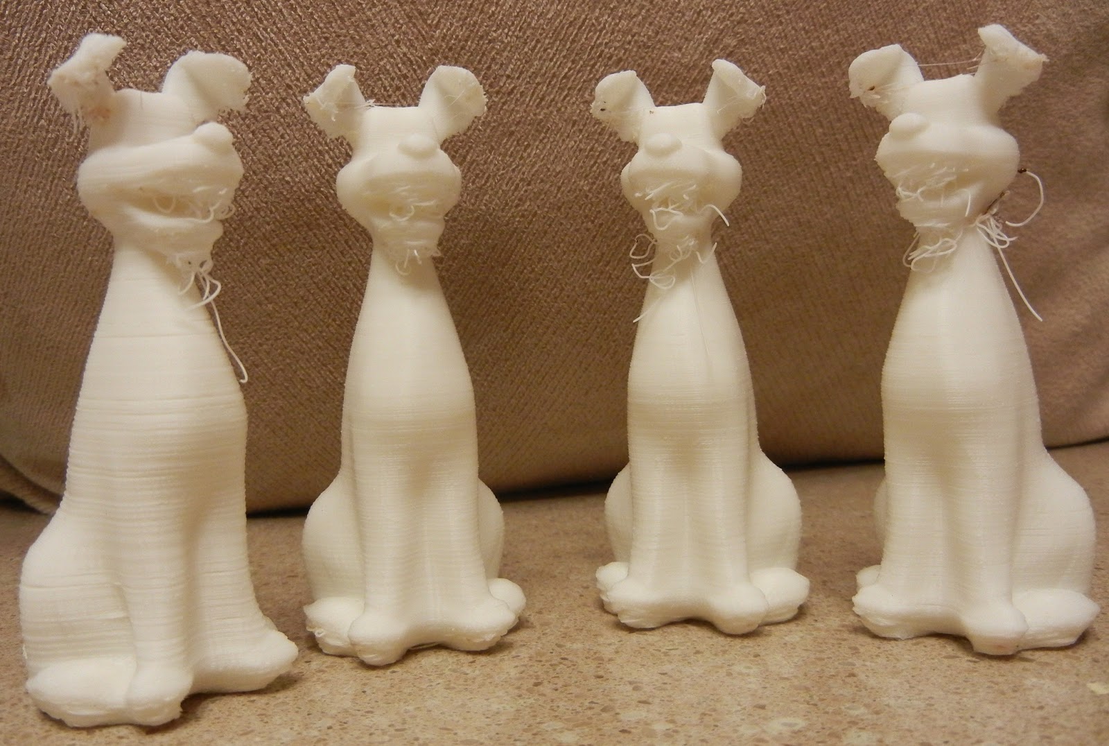
The 4 Dogs, numbered left to right
Dog #1, far left, is 0.2mm layer height with a 1mm Z-lift. I've been using a 1mm lift since the beginning since I was having all kinds of problems with the nozzle hitting ooze piles, jamming the stepper motors, then ruining a print.  In this dog you can see some variability in layers, some gaps visible, etc. Lots of stringies from the bottom of the mouth and ears also.

Dog #2: Since the new nozzle doesn't ooze nearly as much, I thought I'd take a chance and get rid of the Z-lift entirely. That made a huge difference- note how uniform and clean each layer is. No issues with skipping steps either. I also reduced the Bridge Flow Ratio (BFR) from 1.0 to 0.95 to try and improve the mouth and nose details. That didn't seem to help much, this dog still had bridging challenges on the mouth and ears.

Dog#3: The final two dogs were meant to fix the bridging entirely- #3 has a BFR of 0.85

Dog#4: BFR of 0.75. Minimal effect.

A fan might be required to get this dog to print nicely. Otherwise a nail file and wire clipper will clean it up nicely.

How about trying a vapor polish? Just don't leave it in there too long like I did. It's also a smart idea to let the vapor chamber fill first, before inserting your part. Otherwise the bottom of the part gets over-polished and the top gets under-polished. Here is what it looked like after 45 minutes:

Melted Dog!
 The bottom of the dog was very, very soft and had partially collapsed and the top still looked good.


Next, now that small part performance is starting to look pretty good, I thought I'd actually do something useful with the printer. I installed some under cabinet LED lights from amazon.com. These were very nice- decently warm color, and easy to install. However, I needed a better solution to fasten the wires in place to the bottom and inside of the cabinets. Neither Home Depot or Lowes had appropriate wire clips or staples, so I thought I'd design and print my own. All of the commonly available clips are made for coax cables, CAT5, romex, etc.


These custom clips securely clamp the wire in place and attaches using a #6 flat head screw. The .STL file, part model, and dimensions are available now on thingiverse.


tags: mendelmax 1.5, rep rap

Tuesday, April 2, 2013

More MendelMax 1.5 reprap improvements....

The original vinyl tubing Z-axis connector was showing it's age- starting to crack and slip. The version of MendelMax 1.5 I built uses a 3/8 inch ACME thread Z-axis threaded rod- so it's not easy to find a drop-in replacement My first try at an improved Z-axis connector was to design and print one. This connector can be found on thingiverse.

Printed 3/8" ACME to 5mm Stepper connector, installed

Printing parts with the new connector
The new connectors didn't work quite as well as the vinyl tubing- and seemed to introduce a good wobble to the Z-axis threaded rods, and thus made the parts print with irregularities in the layer thickness.

Unfortunately nice machined aluminum couplers are not available to join 5mm shafts to 3/8" ACME rod. I was able to find some very inexpensive 5mm to 8mm aluminum flex couplings on e-bay. Then, a friend helped me turn down 0.5" of the shaft end to 8mm to fit the couplings.

3/8 ACME rod with end turned to 8mm
Coupler Installed
I've also been fighting part warping. I thought one way to combat this would be to control airflow, and to keep the air around the printed part still and fairly warm. I found some thin acrylic sheet at the local Lowe's hardware store. It cut very nicely by scoring it with a knife and also with a bandsaw.

Cutting Acrylic Sheet
Material Detail

Draft Guards installed


Thursday, March 7, 2013

Little Tikes replacement parts + Replacement Y Axis

Little Tikes Replacement Parts
What better way to utilize a high tech factory at home than to use it to make replacement parts for kid's toys?

The hinge brackets for my son's Little Tikes kitchen broke. These seem like a normal wear item, but they are quite expensive to buy- you can't buy just the hinge bracket, Little Tikes forced you to buy a kit with a range of fasteners. But, with a printer it's cheap and easy to replace. Very easy to draw up in Solidworks and print out... And they turned out really well. But, they aren't "kid tested" yet. That'll be the true test!

The solid models are available on thingiverse here.

"Real" Bracket on the left, new printed brackets center and right

Installed on the "oven" door

Works fine!

Updated Y Axis

My original Y axis was home made. It worked pretty well, but it limited the Y axis build size to 160mm, it was really difficult to level, and it was solid mounted. The solid mounting might have been the cause of some of the skipped steps, as if the nozzle hit a glob of plastic during a traverse it could stop the traverse. With a spring loaded bed, the bed can flex away from the nozzle. After considering machining my own parts, I decided to save the time and just buy the set from lulzbot.com. They turned out to be nice high quality laser cut parts, assembled easily, and fit perfectly.

New bed plate (and 5mm SHCS heads visible)

Assembly, bottom 3/4 view
Assembled and in MendelMax 1.5

I had to mount the Y-axis endstop in a new location- once I have a good mount design I'll post some photos.

Printing a spare X-slide on the new Y axis


Wednesday, February 27, 2013

Stepper Driver Replacement + Vapor Polishing ABS

New Pololu A4988 Black Edition stepper drivers
I've been having problems with the X and Y axis on my MendelMax 1.5 reprap losing steps. After checking to make sure both axis has free motion, and double checking the power settings, I thought it might be caused by the cheap www.gadgets3d.com A4988 stepper drivers I was using. So, I ordered some genuine Pololu A4988 "Black Edition" drivers directly from www.pololu.com. These do require some minor soldering to attach standard header pins to the circuit board. The "Black Edition" drivers have a thicker copper layer in the PCB to better handle heat dissipation.

Parts as received from Pololu
Stepper Driver & Header pins, ready for action

Cutting Header pins in half with a small side cutter

Header pins pressed into standard breadboard- will hold pins in alignment  during soldering for easy insertion into RAMPS board.
Applying flux to header pins. Note short end of the pins are soldered to board

Applying flux to solder pads on board
Ready for soldering

Finished, soldered product
 I inserted the new boards into the X, Y, and Z axis. Problems.... The Z worked just fine, and stayed cool to the touch. However, the X and Y had issues- part of the way through some sample prints each axis simply stopped working period. I switched back to the original gadgets3d drivers until I can troubleshoot the problem. The new Pololu drivers do run much, much cooler than the gadgets3d drivers.

 Vapor Polishing ABS printed objects
I saw online that some people have been experimenting with vapor polishing printed objects to produce a really nice surface finish. This blog has a great step by step instructions on how to do it.

Polishing example, courtesy of RepRap:Blog

I decided to try this on some parts I printed for my Rep Rap.


LCD bracket, as printed @ 0.2mm layer height


Vapor Polishing - 3mm of acetone in bottom of jar heated to 90 degrees C on hot plate.  
Once the vapor has formed to the height of your part, place your part in the jar on top of some sort of removable support. Be very careful with this- it can be a fire / explosion hazard and the acetone vapors are a health hazard. Leave it in as long as you want, you can visually see the part smoothing out. Remove the part, and let sit until cured.

Vapor condensate layer visible on glass. Part was left in beaker for about 15 minutes
Finished, Polished par.t Be sure to allow the part to fully cure- all the acetone to evaporate out of the part. It may be possible to bake out the part at a low temperature to speed the process. The finished part has a glassy sheen.
LCD screen mounted on MendelMax. I'll upload this to www.thingiverse.com when I have the design a bit more polished.

Thursday, February 14, 2013

Quick Update

I've been spending a lot of time trying to get the rep rap mendelmax tuned. I'll be posting some photos later, but here is a quick summary of what I've learned:


1) X and Y axis losing steps- I spent a bunch of time tweaking the pots on the stepper drives, and couldn't totally eliminate the problem. I'd get 1/2 way through a print, and it would lose some steps and ruin the print. Eventually I tried reducing the x/y "jerk" setting in the Marlin firmware, as suggested by some people on the mendelmax google group. That seemed to work pretty well.
2) tangling of the filament jamming up the system - I printed out a cool filament spool holder right after I was able to get the printer running. For the most part it worked ok, but I was getting random tangles where a few wraps of filament would come off the spool and get tangled with something, jam up the X axis, and cause a lot of missed steps, thus ruining the print. Right now I've stopped using the overhead spool mount (currently shown in the photos in earlier blog postings) and I have the spool off to the side of the printer on a dowel. I think I'm going to rig up something with a guide tube to keep the filament under control so I can go back to using the overhead spool mount.
3) filament feed problems into the extruder- I've learned that your extruder MUST keep the filament properly aligned with the hobbed bolt, otherwise the filament will slowly drift off to the side and stop feeding properly. I ended up putting a couple guide pins into the extruder idler piece to do this. I also was able to order some M3 x 50mm SHCS so I could use springs to keep an even compression on the idler, rather than just cranking down the screws. 
4) 1st layer adhesion- I'm using "abs juice"- ABS dissolved in acetone - painted onto the glass build plate. That works pretty well to keep the first layer stuck down during the print. This, in conjunction with a 100 or 110 degree C build plate works OK. I'm still getting a little lift / warping at the ends of large parts. I've also used blue painter's tape with the hot bed. This seems to work OK for small parts (1" or 2" on a side max), but parts any larger tend to warp and pop off before the print completes.
5) z-lift- enable the z-lift between moves on your slicer- I'm using a 1mm lift- this helps reduce breaking the part off the build platform during prints. 

Wednesday, February 6, 2013

First 3D printed bike project

My first home-made bike part on the 3D printer- a rear light mount for my Surly Big Dummy. When I have the baby seat mounted on the back of the bike, my rear flasher is blocked. That's obviously not safe- so I wanted to make a mount that was super solid, wouldn't be blocked by the baby seat, and wouldn't get in the way of any of the bike's cargo capabilities.

I designed the parts using Solidworks 2012, and printed them on my rep rap Mendelmax 1.5. 

Printing the clamps

Stock mount and light on top, new mount on the bottom

Light mounted on the new clamp mount


Mounted to the bike and ready to go

MendelMax 1.5 Build Log: Part 8, Fixing Extruder

I'm using one of the Greg's Wade Extruder variants, and the small tabs that were meant to keep the filament in alignment with the hobbed bolt broke off. Initially I just used a small piece of plastic jammed into the extruder to keep the filament in line, but that proved to be unreliable. (surprise, surprise) Rather than print out a new extruder idler, I decided to simply drill and tap a hole to mount a 2/56 SHCS as an guide.

Drilling hole for 2/56 screw (0.075" approximate)

Screw Mounted
The screw guide worked great, and totally solved the issues I was having with the filament slipping off of the hobbed bolt and causing a print to fail.

MendelMax 1.5, spool holder mounted and wires cleaned up