Ubuntu 13.04 Linux w/ Repetier Host
I started having issues driving my MendelMax 1.5 (Marlin firmware) with my creaky old HP Vista laptop after I "upgraded" to Repetier Host 0.90c. STL files wouldn't visualize when imported into the model placement window. Rather than try and track down a Windows 7 license for the old laptop to fix this issue, I decided to try Linux, and I was able to obtain an old obsolete T61p Lenovo laptop from my employer for a nominal cost.
To my surprise, Ubuntu 13.04 installed extremely easily with no driver problems at all. Even the keyboard volume and contrast keys worked. The Repetier Host install (found here) was a bit of a pain to install, requiring a separate installation of Mono. I still can't get Repetier host to run any way except typing the command into the command line. I'll have to do some additional research to fix this- ideally I could pin it to the left hand application bar.
Once installed and running, I could not get it to talk with the printer. I've used this laptop with this exact Ubuntu installation to program Arduino boards before, so I knew it should be able to communicate successfully. After some web searching, I saw that Mono doesn't support the default Repetier Host / Marlin firmware baud rate. I went into the Marlin firmware, updated the Baud rate to 115200, recompiled, and updated the Repetier Host settings. Bam, worked!
Question- is the Repetier firmware any good? Would it be worth changing from Marlin to Repetier?
Solidworks on personal Laptop, RAM upgrade
I have the home license for Solidworks (2013, 64bit, SP04) installed on a two year old laptop running Windows 7 with 6Gb of RAM. This laptop has an i7 processor with a decent consumer graphics card, so it should have run Solidworks pretty well, at least for simple models. But, it had all kinds of graphics window stuttering, making modeling really annoying. I've thought about upgrading the RAM for the last year, but didn't want to spend the money because I wasn't sure it'd fix the issue. I finally purchased a 8Gb stick so I could upgrade the RAM from 6 to 12Gb- and that was absolutely the ticket. It isn't perfect, and doesn't run as well as my desktop at work, but it gets the job done. No more mystery stuttering. So if you are wondering if the RAM upgrade is worth it, just do it.

Tuesday, September 17, 2013


Monday, September 9, 2013
Littermaid Litterbox fix w/ Arduino
Our Littermaid automatic litter box decided to die a week or two before a week long vacation- exactly when it needs it to work. The motor appeared to be fine- just when plugged in, it would try to return to home position, reach it, and the motor would continue to grind away until the electronics timed out. Then, no more activity. I opened it up and pulled the circuit board out. I hoping to find an obvious problem- burned components or other clues to what failed. Nothing was obvious. I also tested both limit switches, and both seemed to be fine. The motor also easily turned when it was fed 12V DC. Instead of troubleshooting each component, I decided to completely replace the stock electronics with an Arduino and a motor driver shield.
After examining the dissembled litter box, I found a pretty simple machine:
The actual wiring of the project was pretty straightforward- basically hook everything up, make sure the appropriate pull-down resistors were in place, then start writing some code. I first wired everything using a standard breadboard, then once it worked I transitioned the parts to a permanently soldered perfboard.
I'm no codewarrior, so I wrote the arduino code as simple as possible, with lots of comments. There is also lots of feedback through the serial window to aid in debugging.
Use this project, details, etc at your own risk!
After examining the dissembled litter box, I found a pretty simple machine:
- 12v DC Gear motor for driving the rake
- Limit switches for home and maximum travel
- IR LED / Phototransistor to detect the cat
I wanted this to be as inexpensive and easy as possible of a project, so I chose to re-use all of the stock sensors and motor.
Since an Arduino can't supply the required power or voltage to control the motor, a separate motor driver is needed. I chose to use a Seeedstudio motor drive shield as it was available at the local RadioShack store. This shield is also nice because it'll supply power to the Arduino it is attached to. One big negative, though, is that all of the I/Os are all proprietary "grove" connectors which RadioShack doesn't sell except in a $50 kit.
 |
| Seeed Studio Motor Shield |
I did a bunch of searching on the internet to try and find a local solution, or at least one that didn't require ordering parts from China. (Seeed Studios ships from China, not a domestic warehouse) Since I needed to finish this project relatively quickly, I couldn't wait for some parts to arrive from across the Pacific. Sparkfun does carry a cable / connector assembly that is really close. It fits after some modification with a X-acto knife.
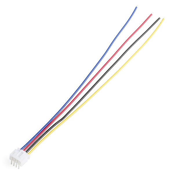 |
| Sparkfun JST Jumper 4-Wire Assembly |
The actual wiring of the project was pretty straightforward- basically hook everything up, make sure the appropriate pull-down resistors were in place, then start writing some code. I first wired everything using a standard breadboard, then once it worked I transitioned the parts to a permanently soldered perfboard.
 |
| Fritzing illustration of breadboarded setup |
I'm no codewarrior, so I wrote the arduino code as simple as possible, with lots of comments. There is also lots of feedback through the serial window to aid in debugging.
Use this project, details, etc at your own risk!
Arduino Code:
/*
Littermaid catbox control
uses Seeed studio motor shield
portions of code from Seeed example code
*/
// set up sensor & switch pin locations
int sensorPin = A0; // select the input pin for the cat presence sensor
int endPin = 3; // select the input pin for the endstop
int homePin = 4; // select the input pin for the home endstop
// set up motor pin locations, set by the motor shield used
int pinI1=8; //define I1 interface
int pinI2=11; //define I2 interface
int speedpinA=9; //enable motor A
int spead =255; //define the spead of motor
// set up various delays
int sensorloopdelay=500; //delay in ms between loop repetitions when waiting for cat
unsigned long delayaftercat=600000; //delay in ms before cycling catbox after cat is detected, 10 minutes
// set up default sensor values
int sensorValue = 100; // variable to store the value coming from the sensor. starting at 100 so no cat present
int endValue=1; // endstop status
int homeValue=1; // home stop status
unsigned long MaxTravelTime=30000; //maximum time for rake to travel each direction, assumes jammed if didn't finish in alloted time
void setup() {
// initialize the various inputs and outputs
pinMode(endPin, INPUT);
pinMode(homePin, INPUT);
pinMode(sensorPin, INPUT);
pinMode(pinI1, OUTPUT);
pinMode(pinI2, OUTPUT);
pinMode(speedpinA, OUTPUT);
//set up serial communications with computer
Serial.begin(9600);
}
void loop() {
// run catbox cycle
int success=0; // cycle success (1) or failure (0)
int i=0; // loop counter
Serial.println("cat box cycle start");
while (i < 5)
{ // run cycle maximum of 5 times, stop when cycle is successful
success = cycle();
Serial.println(success);
if (success != 0) // break out of 5 rep loop if cycle did not fail
{
Serial.println("successfull cycle");
i=5; // break out of loop
}
else
{
Serial.println("unsuccessful cycle");
i=i+1; //increment i
}
}
// reset sensor value
sensorValue = 100;
// wait until cat is detected
Serial.println("waiting for cat");
while (sensorValue > 10)
{
// read the value from the sensor
// if > 10 no cat
// if < 10 cat is present - loop until cat is present
sensorValue = analogRead(sensorPin);
Serial.println(sensorValue); //print sensor value for troubleshooting
delay(sensorloopdelay);
}
Serial.println("cat detected");
// wait until cat leaves
while (sensorValue < 10)
{
// read the value from the sensor
// if > 10 no cat
// if < 10 cat is present - loop until cat is present
sensorValue = analogRead(sensorPin);
Serial.println(sensorValue); //print sensor value for troubleshooting
delay(sensorloopdelay);
}
Serial.println("cat left, waiting for specified period of time");
// wait for specified period of time before running catbox cycle
delay(delayaftercat);
}
int cycle() //returns successful cycle or failure
{
unsigned long startMove_time=0;
unsigned long time_elapsed=0;
int success=0;
Serial.println("start motor out");
Serial.println("wait until endstop");
// wait until endstop is reached
startMove_time = millis(); // find time immediately before move start
backward(); // start motor towards endstop
Serial.println("moving towards endstop");
while (endValue != 0 & time_elapsed
{
time_elapsed= millis()-startMove_time; // calculate time elapsed
endValue=digitalRead(endPin);
}
stop_motor();
if (endValue==0)
{
Serial.println("endstop reached");
success=1;
}
if (time_elapsed >= MaxTravelTime)
{
Serial.println("outbound travel timed out");
success=0;
}
endValue=1; //reset endstop value
Serial.println("stop motor");
Serial.println("reverse motor");
Serial.println("wait until home stop");
startMove_time = millis(); // find time immediately before move start
time_elapsed=0; //reset time elapsed
forward(); // start motor back towards home
Serial.println("moving towards home");
while (homeValue != 0 & time_elapsed
{
time_elapsed= millis()-startMove_time; // calculate time elapsed
homeValue=digitalRead(homePin);
}
stop_motor(); // stop motor
if (homeValue==0)
{
Serial.println("home stop reached");
success=1;
}
if (time_elapsed >= MaxTravelTime)
{
Serial.println("inbound travel timed out");
success=0;
}
homeValue=1; //reset home stop value
Serial.println("stop motor");
return success; //return value back to main loop
}
void forward()
{
analogWrite(speedpinA,spead);//input a simulation value to set the speed
digitalWrite(pinI2,LOW);//turn DC Motor A move anticlockwise
digitalWrite(pinI1,HIGH);
}
void backward()//
{
analogWrite(speedpinA,spead);//input a simulation value to set the speed
digitalWrite(pinI2,HIGH);//turn DC Motor A move clockwise
digitalWrite(pinI1,LOW);
}
void stop_motor()//
{
digitalWrite(speedpinA,LOW);// Unenble the pin, to stop the motor. this should be done to avid damaging the motor.
delay(1000);
}
MendelMax 1.5 Stepper Motor Upgrade - no more skipped steps!
Ever since the first test prints on my MendelMax 1.5 reprap 3D printer, I've been struggling with skipped steps and layer mis-alignment in my X and Y axis. I've spend much time getting my X and Y axis as smooth and friction-free as possible, upgraded the stepper drivers, and adjusted the acceleration and jerk settings. These all helped, but nothing completely eliminated it. A couple weeks ago I finally decided to try some different stepper motors.
The motors I originally built the machine with were sourced from a industrial salvage yard, and didn't come with any sort of specifications other than they were a NEMA 17 case size and bipolar. (4 leads) I did see someone else's MendelMax with "store bought" steppers and I was shocked at how much longer the cases were and how fast he could get the X and Y axis to accelerate.
So, finally I decided to bite the bullet and purchase a pair of steppers from www.lulzbot.com. I've purchased other items from them in the past and they've always had good quality parts. I also bought a 0.35mm nozzle for the extruder as well. The 0.5mm I started with originally seemed "too big", and the 0.25mm I tried next was "too small". I was hoping the 0.35mm was "just right."
New Stepper motor specs:
As you can see, the new steppers are much longer than my original steppers. They proved to have a corresponding increase in torque.
The combination of the new X-Y steppers and 0.35mm nozzle has been great so far. No issues at all with step skipping- the nozzle just blasts through drips during traverses across the part during prints. The printed parts also seem to be more accurate and have cleaner details. I did slightly adjust the voltage going to the X and Y axis using the standard procedure without any trouble. Both Z-axis and the extruder stepper motor are still the original small steppers. I might upgrade the extruder stepper at some point in the future, as I've noticed it skipping steps occasionally. The Z-axis steppers work just fine though.
One of the first parts I printed was a new, improved design I modeled for a swiffer replacement part. (found on Thingiverse here) It's a challenging part because of the internal thread to engage the swiffer handle- it requires clean bridging and good accuracy for the threads to fit correctly. The part fit great, much better than previous attempts. This is good because our toddler loves to swing it around and break this particular part. I printed the last attempt using a 80% fill, hopefully that is strong enough to last a while.
Next up was to upgrade the gears on the extruder. The original straight cut gears were getting noisy with a lot of backlash during printing. I chose to print these Herringbone gears off of thingiverse. They printed very well, and easily assembled. The nut trap in the small gear was very precise, and the nut dropped right in- something I had trouble with previously. The new gears run well with little or no backlash.
I'm considering upgrading the extruder to a belt drive unit and getting rid of the printed gears entirely. A belt drive would have zero backlash, and wouldn't wear out. The 00str00der on thingiverse looks interesting. The only problem is the belts and GT2 timing pulleys are tough to find, particularly at a reasonable price.
The motors I originally built the machine with were sourced from a industrial salvage yard, and didn't come with any sort of specifications other than they were a NEMA 17 case size and bipolar. (4 leads) I did see someone else's MendelMax with "store bought" steppers and I was shocked at how much longer the cases were and how fast he could get the X and Y axis to accelerate.
So, finally I decided to bite the bullet and purchase a pair of steppers from www.lulzbot.com. I've purchased other items from them in the past and they've always had good quality parts. I also bought a 0.35mm nozzle for the extruder as well. The 0.5mm I started with originally seemed "too big", and the 0.25mm I tried next was "too small". I was hoping the 0.35mm was "just right."
New Stepper motor specs:
- Step angle: 1.8°
- Holding torque: 55 N.cm
- Rated voltage: 2.8V
- 2 phase
- Resistance per phase: 2.8?,±10%
- Inductance per phase: 4.8?,±20%
- Operation temp range: -20°C ~ +50°C
- Wieght: 0.365Kg
- 4 AWG22 lead wires (ends are bare and need connectors)
- 5mm D-shaped motor shaft
 |
| Original motor on the left, new motor on the right |
The combination of the new X-Y steppers and 0.35mm nozzle has been great so far. No issues at all with step skipping- the nozzle just blasts through drips during traverses across the part during prints. The printed parts also seem to be more accurate and have cleaner details. I did slightly adjust the voltage going to the X and Y axis using the standard procedure without any trouble. Both Z-axis and the extruder stepper motor are still the original small steppers. I might upgrade the extruder stepper at some point in the future, as I've noticed it skipping steps occasionally. The Z-axis steppers work just fine though.
 |
| Swiffer replacement part |
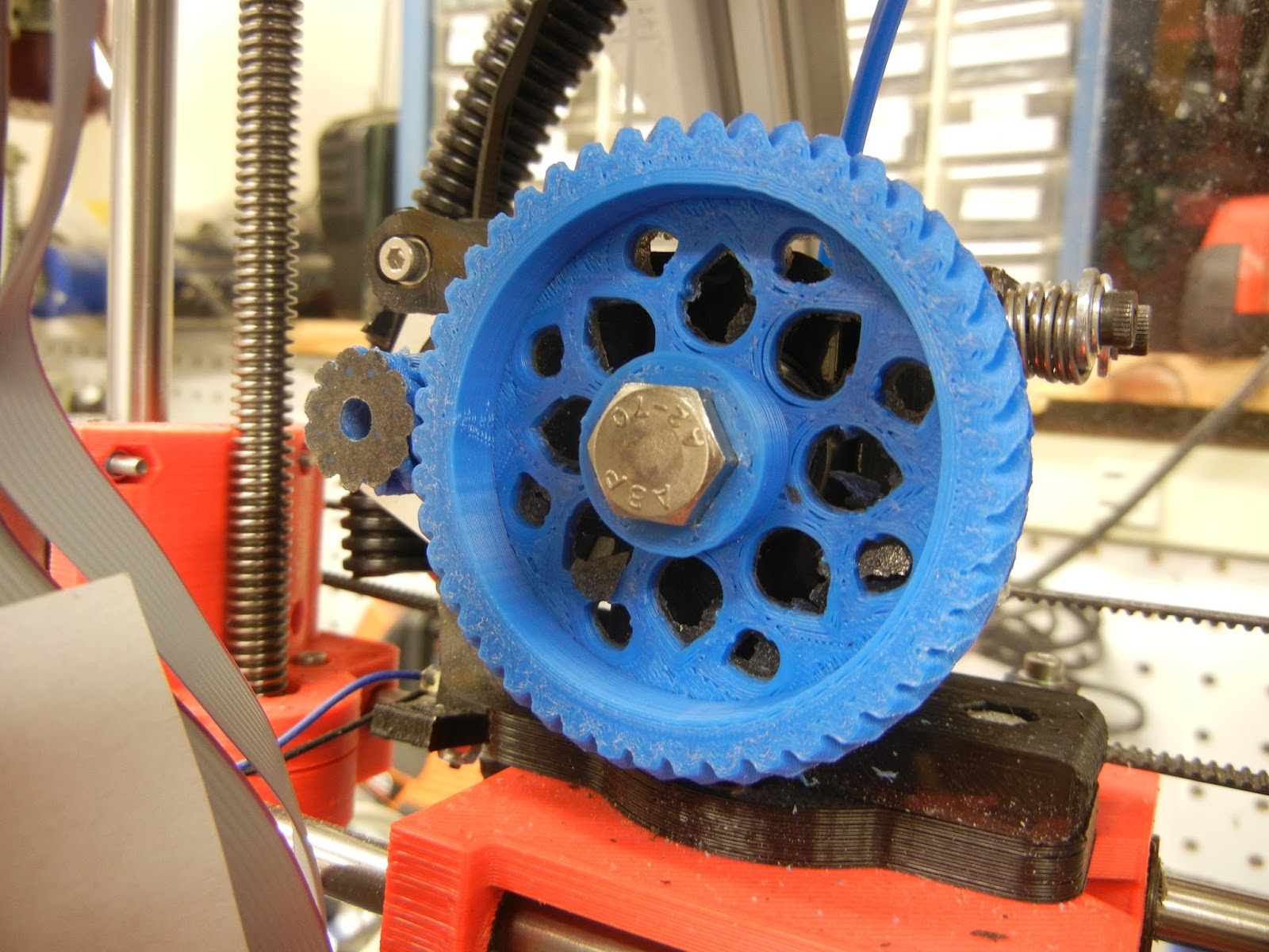 |
| New Herringbone Gears |
I'm considering upgrading the extruder to a belt drive unit and getting rid of the printed gears entirely. A belt drive would have zero backlash, and wouldn't wear out. The 00str00der on thingiverse looks interesting. The only problem is the belts and GT2 timing pulleys are tough to find, particularly at a reasonable price.
Wednesday, September 4, 2013
Octave 3D Printer Enclosure mini-Review
After trying several home-baked options for our lab Afinia 3D printer, I purchased a Octave 3D printer enclosure from www.octave.com. We wanted some way to control the air currents and air temperature around the printer. Our lab can be drafty and prone to big temperature fluctuations depending upon how hard the AC is blowing and if the sun is particularly strong. The Octave enclosure seemed like a very reasonably priced option.
The enclosure arrived pre-assembled in a big cardboard box within a few days after ordering. I think I was fortunate that I ordered it quickly after seeing the advertisement- Octave's website says they are currently back-ordered now.
The enclosure is a nicely designed ABS plastic box, with a clear plastic door. There is a slick trap door on the top for loading new filament into the extruder head, complete with a slot allowing for free motion during printing. My only nitpick would be to make the door another inch or two wider to the left, to allow for easier filament loading when the print head is in the full left "home" position.
Another door in the back of the enclosure allows for easy access to the Afinia's power and USB ports.
The Afinia's feet fit into sockets on the enclosure base plate, keeping it solidly in position during prints. Rubber feet on the bottom of the enclosure keep it anchored to your desk top or bench top.
A fan with charcoal filter ventilates the box, and a set of LED lights inside the enclosure keeps your print job brightly illuminated. I was a bit disappointed that there was no on/off switch for the fan and lights. To turn them on and off you must plug/unplug the included AC power adapter. I called Octave, and they said future versions would include an AC adapter with a switch, and would send me one when it is available.
The enclosure didn't include a spool mount. But, Octave makes 3D models of some mounts available on their website for download and printing. Another very minor nitpick is the arm that holds the "outboard" end of the filament tube doesn't fit the filament quite right- the filament doesn't "snap" into the slot at the end of the arm. The slot could stand to be a few thousands of an inch narrower, with a larger interior thru-hole for the filament. If this proves to be an issue I'll model a new arm and post it on thingiverse.com.
Overall, I'd recommend this enclosure for purchase if you own an Afinia 3D printer. I can't yet say if it measurable improves print quality, but seems like it should.
Pros:
 |
| Afinia happily printing away in its new home |
The enclosure arrived pre-assembled in a big cardboard box within a few days after ordering. I think I was fortunate that I ordered it quickly after seeing the advertisement- Octave's website says they are currently back-ordered now.
The enclosure is a nicely designed ABS plastic box, with a clear plastic door. There is a slick trap door on the top for loading new filament into the extruder head, complete with a slot allowing for free motion during printing. My only nitpick would be to make the door another inch or two wider to the left, to allow for easier filament loading when the print head is in the full left "home" position.
 |
| Super slick top trap door & filament slot |
Another door in the back of the enclosure allows for easy access to the Afinia's power and USB ports.
The Afinia's feet fit into sockets on the enclosure base plate, keeping it solidly in position during prints. Rubber feet on the bottom of the enclosure keep it anchored to your desk top or bench top.
A fan with charcoal filter ventilates the box, and a set of LED lights inside the enclosure keeps your print job brightly illuminated. I was a bit disappointed that there was no on/off switch for the fan and lights. To turn them on and off you must plug/unplug the included AC power adapter. I called Octave, and they said future versions would include an AC adapter with a switch, and would send me one when it is available.
The enclosure didn't include a spool mount. But, Octave makes 3D models of some mounts available on their website for download and printing. Another very minor nitpick is the arm that holds the "outboard" end of the filament tube doesn't fit the filament quite right- the filament doesn't "snap" into the slot at the end of the arm. The slot could stand to be a few thousands of an inch narrower, with a larger interior thru-hole for the filament. If this proves to be an issue I'll model a new arm and post it on thingiverse.com.
 |
| Approximate 30 degrees C interior temperature (blue tape holding thermocouple wire in place) |
Overall, I'd recommend this enclosure for purchase if you own an Afinia 3D printer. I can't yet say if it measurable improves print quality, but seems like it should.
Pros:
- Nicely designed & constructed unit. It seems to be good quality and should easily last the lifetime of your printer.
- keeps interior at a fairly constant temperature
- LED interior lights a nice touch
Cons:
- No on/off switch (yet)
- Filament arm design could use a little more polishing
Wednesday, August 7, 2013
Xtracycle Kickback Kickstand Fixes
I've had the Xtracycle Kickback kickstand on my Surly Big Dummy for a few years now. While it does a great job of holding the bike upright when parked, it's full of small annoyances. As lots of other people online have noted, these small issues seem pretty big when you consider the high price for what is essentially a kickstand.


Bold the rubber foot to the bottom of the frame, using the same mounting hole as the factory kickstand.
- The plastic feet on the bottom of the Kickback wear out really fast, and soon your bike is being held upright by a pair of aluminum tubes, which can scratch the heck out of whatever you are parking on.


2. The Kickback makes really annoying clunking / clacking noises when you hit a bump, jump a curb, or try to do "fun things" with your cargobike.
This is a bit bigger problem. For some reason Xtracycle didn't use a spring design like most motorcycle centerstands or regular bicycle kickstands- they just used a regular extension spring encased in a nylon bag. As a result, when the Kickback is retracted, the spring force holding the kickstand in place is pretty low, allowing it to flop around and bang into your bike's frame.
I've been looking at some other spring options and possibly even designing some sort of over-center mechanism, but haven't finished anything that is ready for road use. However, there is a simple fix to drastically reduce the amount of noise the Kickback makes when it flops around.
Simply mount a rubber bumper to the underside of where the factory kickstand mounts. It seems to work pretty well. You can still hear it banging around after a curb drop, but it is much, much quieter. Another option might be to put one of the rubber chair feet onto the steel stub on the kickback.
Materials Needed:
- Rubber foot with thru-hole, appropriate size
- Screw, nut, and washer of appropriate size to fit through rubber foot
- Threadlocking compound
 |
| Materials Needed |
 |
| Rubber foot mounted, Kickback down |
 |
| Rubber Foot Mounted, Kickback up |
Saturday, May 25, 2013
Z-Axis Endstop, Micrometer Head Adjust
I was still not having good luck consistently getting the z-axis endstop to zero my MendelMax 1.5 rep rap Z-axis in the right place. Using a 4/40 or M3 screw just didn't provide the vertical resolution that I needed to really zero in the axis. So, I decided to really do it right and use a micrometer head to provide extremely fine adjustments.
I found this great Mitutoyo micrometer head on e-bay- a $150 unit for $20, shipped. Second hand industrial surplus is great.
So, instead of trying to fumble with turning a unlocking nut, then a screw only a couple degrees, then locking the nut again- all you have to do is twist the dial and watch exactly how far you move the tip up or down. Very easy.
I updated the Z-axis screw holder to accommodate the new micrometer head and printed it out.
Everything seemed to fit well, and I uploaded the finished design to thingiverse, download the files here.
So far it seems to work great- it's a lot easier to dial in the nozzle height. Some people claim that adjusting this in software is easier, but for me twisting a knob and immediately running the program again is the most convenient way to go.
To give it a try I ran the old standby- the 5mm calibration object pyramid. It looks better each time. I'm still puzzling at how to get the top block square, and the bridging tests aren't super clean. (visible on the back of the pyramid)
Maybe adding a fan would clean up the bridging and some of the odd sidewall shrinkage?
With the hot-rodded printer, I designed and printed a replacement part for the swiffer. The piece that connects the handle to the mop head broke. It's a challenging part- it has a large internal ACME screw thread to join it to the handle. To my amazement it threaded right on, no cleaning of the threads needed. So far it seems to work just like the "factory" part. Download this part here.
I found this great Mitutoyo micrometer head on e-bay- a $150 unit for $20, shipped. Second hand industrial surplus is great.
 |
| Mitutoyo 148-811 Micrometer Head |
I updated the Z-axis screw holder to accommodate the new micrometer head and printed it out.
 |
| Mount for Micrometer Head |
 |
| Everything Mounted and ready to go |
 |
| Front view |
So far it seems to work great- it's a lot easier to dial in the nozzle height. Some people claim that adjusting this in software is easier, but for me twisting a knob and immediately running the program again is the most convenient way to go.
To give it a try I ran the old standby- the 5mm calibration object pyramid. It looks better each time. I'm still puzzling at how to get the top block square, and the bridging tests aren't super clean. (visible on the back of the pyramid)
 |
| 5mm calibration object test |
 |
| Back of Pyramid |
With the hot-rodded printer, I designed and printed a replacement part for the swiffer. The piece that connects the handle to the mop head broke. It's a challenging part- it has a large internal ACME screw thread to join it to the handle. To my amazement it threaded right on, no cleaning of the threads needed. So far it seems to work just like the "factory" part. Download this part here.
 |
| Swiffer with new head mount |
 |
| Closer view |
Wednesday, May 1, 2013
Z-Axis Endstop Switch Update
I'm still having a challenge getting the nozzle height correct for prints- and part of it seemed to be some inconsistency in the Z-axis homing / endstop. The stock Z-axis endstop switch is a standard microswitch. Doug suggested that I remove the spring arm from the switch. Doing this should remove at least some variability from the Z-axis homing cycle.
So far no definitive data on if this actually improves anything, but I don't see how it can hurt.
 |
| Z-Axis endstop microswitch with metal spring lever attached |
 |
| Spring Lever "Removed" |
 |
| Switch back in position and ready to go |
Subscribe to:
Posts (Atom)