
Unfortunately after reading through the reprap.org forum on the FD, it seems like I may have bought the board much too early from Geeetech- the board I received is the v1 rev A, and the guys developing it haven't even finished the development process yet.... So lots of know issues with this board. I guess I'll just have to jump in and see if I can get it running, and if it's too much trouble switch back to a traditional RAMPS 1.4 setup.
The 'official' documentation and other blog postings on this board is a bit thin, so I'm crossing my fingers that I'm able to get it up and running successfully.
I did find the board schematic: http://www.geeetech.com/wiki/index.php/File:RAMPS-FD-Schematic.pdf
along with a wiki page on Geeetech's website: http://www.geeetech.com/wiki/index.php/Ramps-FD
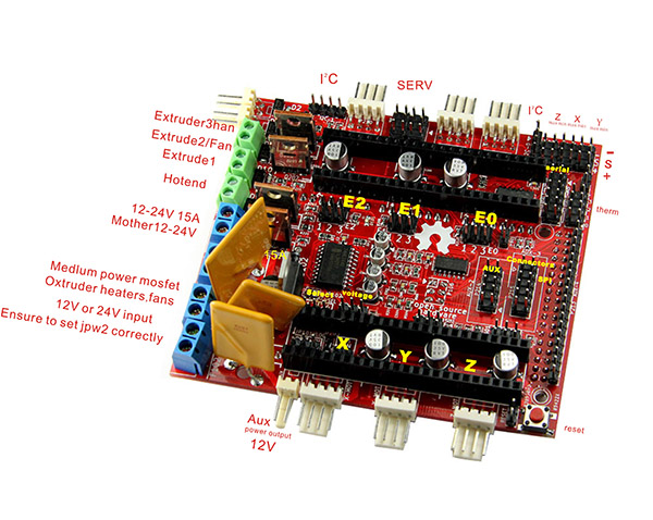
Geeetech does have a rather uniformative labeled picture:
this forum has some information as well: http://forums.reprap.org/read.php?13,244284
My first action was to try and determine the polarity of the power inputs- I really don't want to fry the board because I had my power supply hooked up backwards. When I was looking through the schematic I noticed a critical jumper that needed to be changed- JP102 specifies the board input voltage. 1-2 specifies 24v, and 2-3 specifies 12v. On my board it seemed to be incorrectly labeled- it reads as 1-2 2-4. I guessed the 2-4 pin spot was correct for my 12v power supply.
Next up was the actual polarity of the power inputs- helpfully all of the printed pin numbers are completely covered by the wire sockets on my board. The schematic seems to indicate P107 (motors only), P108 (extruder heater, fans), P101 (heated bed) all have a common scheme- #1 pin ground and #2 pin power/hot, but these pin numbers are not visible on the board.
This photo of a prototype RAMPS-FD board (from Reprap.org forum) seems to show the ground wires on the "bottom" of the board and the "power" wires "higher" on the board:
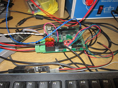 |
| http://farm4.staticflickr.com/3708/9720665422_00f63658d4.jpg |
Hi! What about continue of the post? :) Do you have full map of all jampers and pinouts for this boards?
ReplyDeleteBuildin' Projects: Ramps Fd Initial Setup >>>>> Download Now
Delete>>>>> Download Full
Buildin' Projects: Ramps Fd Initial Setup >>>>> Download LINK
>>>>> Download Now
Buildin' Projects: Ramps Fd Initial Setup >>>>> Download Full
>>>>> Download LINK Xt
I actually gave up on the FD for now- too much trouble trying to get Marlin or RepetierFirmware to actually complile on a Due. So it's back to a RAMPS 1.4 & Arduino Mega.
ReplyDeleteI got reperier to compile with the beta version of IDE, then select due programming port as the "Board type"...I'm looking for close ups of it wired properly. the image above is the best I've seen so far.
ReplyDeleteI'll have to try again when I have time. My father in law just gave me a Udoo quad core which would be sweet all-in-one solution with the RAMPS FD.
DeleteHi
ReplyDeleteAbout the ground and power connection, seems to be correct Andrew! Look at the back of the FD, theres small connections between the "buttom" connectors and the mass. Il try the same with a delta. Just waiting on the due and the printer parts. How i config the steps and where are the endstopp connectors? Is UP101VLOG for the voltage of the stepper drivers and extensions like display?
1) Prusa has a nice online calculator for stepper steps: http://calculator.josefprusa.cz/
Delete2) the schematic has pin-outs for the endstops: http://www.geeetech.com/wiki/images/8/83/RAMPS-FD-Schematic.pdf
3) not sure about the UP101VLOG....
Ok found something, thanks. But a other question. I have 24v on the P107 and P108, so jumper 1+2!? The stepper and endstops seems to work and also the fan but, ive burned up a fan on 100%. Maybe shoud pin 2+4 mean 24v an the documentation is faulty? I have to make some measurements if i got time for this.
ReplyDeleteAn other issue i have. First time i loadet repetier firmware made with online tool it seems to work, then i made some configs and now i never can connect correctly with repetier host (commands waiting). So i tried out the marlin from bobc and it works (do some pin changes becausse its made for V2 at the time, fans, heaters). Tested several bauds and cache options on repetier and dont find the issue. On marlin ive connectet with 460800.
Could you post your pins.h setup? thanks!!
DeleteWhat changes did you make to the pins.h to make it work?
ReplyDeletehere arethe part from my pins.h. But it dont work for delta in my case. The speppers move on repetier command and i can set bed and heater 0 and 1 on and of. Also the temperatures work. But the steppers more move like cartesian.
ReplyDelete#if MOTHERBOARD == 403
#define RAMPS_FD_V1
#define INVERTED_HEATER_PINS
// No EEPROM
// Use 4k7 thermistor tables
#else
#define RAMPS_FD_V2
// EEPROM supported
// Use 1k thermistor tables
#endif
#define X_STEP_PIN 63
#define X_DIR_PIN 62
#define X_ENABLE_PIN 48
#define X_MIN_PIN -1
#define X_MAX_PIN 30 //2 //Max endstops default to disabled "-1", set to commented value to enable.
#define Y_STEP_PIN 65
#define Y_DIR_PIN 64
#define Y_ENABLE_PIN 46
#define Y_MIN_PIN -1
#define Y_MAX_PIN 38 //15
#define Z_STEP_PIN 67
#define Z_DIR_PIN 66
#define Z_ENABLE_PIN 44
#define Z_MIN_PIN 26
#define Z_MAX_PIN 34
#define E0_STEP_PIN 36
#define E0_DIR_PIN 28
#define E0_ENABLE_PIN 42
#define E1_STEP_PIN 43
#define E1_DIR_PIN 41
#define E1_ENABLE_PIN 39
#define E2_STEP_PIN 32
#define E2_DIR_PIN 47
#define E2_ENABLE_PIN 45
#define SDPOWER -1
#define SDSS 4
#define LED_PIN 13
#define BEEPER -1
#define FAN_PIN 12
#define CONTROLLERFAN_PIN -1 //Pin used for the fan to cool controller
#define PS_ON_PIN 53
#define KILL_PIN -1
#define HEATER_BED_PIN 8 // BED
#define HEATER_0_PIN 9
#define HEATER_1_PIN 10
#define HEATER_2_PIN 11
#define TEMP_BED_PIN 54 // ANALOG NUMBERING
#define TEMP_0_PIN 55 // ANALOG NUMBERING
#define TEMP_1_PIN 56 // 2 // ANALOG NUMBERING
#define TEMP_2_PIN -1 // 3 // ANALOG NUMBERING
#define TEMP_3_PIN -1 // ANALOG NUMBERING
#define TEMP_4_PIN -1 // ANALOG NUMBERING
that looks nothing mike mine....I added this line to the
Delete#if MOTHERBOARD == 37
section:
#define E0_PINS ORIG_E0_STEP_PIN,ORIG_E0_DIR_PIN,ORIG_E0_ENABLE_PIN,
Ok, but the right pins of the arduino has to define for this values!? Seems to be a different firmware? I have this https://github.com/bobc/Marlin from bobc ported marlin version.
ReplyDeleteahhhh excellent. I will try that firmware too. Where did you get a V2?
ReplyDeleteif you are not getting delta movements, there are other options than the ones in pins.h that need to be set for delta. I've been off marlin for a while, but when I try it I will post the options for you.
No i do have V1 but only the heater pins seems to be invertet between v1 and v2. £I have copy the delta part from the configuration.h of the normal marlin version and also parts from another file . Plz post the options.
ReplyDeleteI used this as a starting point when I first used Marlin
Deletehttps://github.com/ErikZalm/Marlin/tree/Marlin_v1/Marlin/example_configurations/delta
But the bobc one looks like it has its own sample config it wants you to start with. you could try and pull out what you need. I plan to start with repetier first, as I think I almost got it to work last time I tried...it turned out that geetech sent me a lemon, and I just got my replacement.
I never tried marlin on the due though, I was using a RAMPS 1.4 then.
DeleteI like to take repetier to but. I tried first time bevore some weeks just the ramps fd and the due and i was able to connect. Then ive changed some parameters like stepping freq and delta measurements (all in online tool with loading my configs) and i could never connect again. tried everithing out from baud up and down, fifo in out, on native and programmer port, DTR settings... every time i have the issue that some commands waiting. On this marlin i can connect and make the steppers do something and heaters working. Whats wrong?
ReplyDeleteFound the reason. In pins.h is still eeprom on 1 even i deactivate it in the online config tool from repetier. Now its working! Set on 0.
ReplyDeleteImportant!
ReplyDeleteThe prints on the board for voltage are lablet correctly. I have have 24v input and on sel pin 1 and 2 i become 24v on the fans and heaters. Its set to pins 2 and 4 there is 12v!
I had the same issue with my replacement FD, the unit would communicate over USB, unless the FD was powered, then USB comm no longer worked...is this what you fixed by ignoring the jumper label's lies?
DeleteNo the jumper just about the issue i had 24v on the outputs. The communication issue i have fixet by change the eeprom value from the board 403 in pins.h from 1 to 0. Because the DUE is searching eeprom forever i no installed i think.
ReplyDeleteBuildin' Projects: Ramps Fd Initial Setup >>>>> Download Now
ReplyDelete>>>>> Download Full
Buildin' Projects: Ramps Fd Initial Setup >>>>> Download LINK
>>>>> Download Now
Buildin' Projects: Ramps Fd Initial Setup >>>>> Download Full
>>>>> Download LINK