The first time I saw video of a delta robot style 3D printer, I decided the next printer I built was going to be a delta. Based on everything I've learned from my MendelMax, I knew I wanted a printer that was as stout and stiff structurally as possible, with a GT2 belt drive. Some of the deltas use spectra fishing line, which to me seems like a troublesome way to drive the mechanism, particularly since the GT2 belts are so reliable.
I decided to try using the Makerslide system for the linear bearings vs. the traditional Rostock bearing rods. This solution seems like a nice way to combine a linear slide with the vertical structural components at an affordable price. I sourced the Makerslide linear slide extrusions and related hardware from Inventables.com.
The Wolfstock style delta-bot seems like a good design. But, I wanted to run the drive belts through the inside of the Makerslide for a cleaner look. I couldn't find quite what I was looking for on Thingiverse, so I started to design my own version.
All of the solid models are my design work, but they are almost all heavily based on the Wolfstock, Kossel, and Rostock printer designs. I'm putting the solid models and .stl files on Thingiverse if you'd like to download them: http://www.thingiverse.com/thing:214848 This being Minnesota in the winter- I decided to call it the "Snowstock Delta Bot."
The parts from Inventables arrived quickly and all seem to be top quality. I'll definitely keep this stuff in mind for future projects- maybe even some light-duty industrial automation. It certainly is much less expensive than traditional linear bearings.
 |
| Linear slide carriage components from Inventables |
 |
| Laying out the parts for the V-grove rollers |
 |
| Pressed in one bearing and a M5x20mm SHCS |
 |
| Using washer to space bearings (so when tightened, compression load is transmitted through bearing hub) |
 |
| Second bearing pressed in to place |
 |
| Spacer washer in place |
 |
| Linear slide carriage assembled |
 |
| Carriage mounted to Makerslide extrusion |
 |
| Eccentric spacer allows for adjusting preload of V-grove wheels against Makerslide rail |
The overall design of the printer is intended to keep the structure as simple and solid as possible. Some of the other designs I've seen on Thingiverse have really large printed parts. I tried to keep the printed parts as small as possible, and utilize more 8020 style extruded pieces. Really large printed parts take excessive amounts of time to print, and I always have problems with part warp-age or other quality problems. Plus, if you can source the 8020 extrusions used from a industrial surplus source it's really pretty inexpensive.
I printed all of the big structural parts using a 0.5mm nozzle with a 0.5mm layer height. I think the thicker layers are stronger than thinner- fewer opportunities for layer separation.
 |
| Base components, one motor mounted to test hole alignment |
 |
| Base components |
 |
| Top corners, including idler pulley mount |
 |
| M5x10mm SHCS, washers, & T-slot nuts ready for assembly |
The first two extrusions are easy to install- locate the screws & T-slot nuts in the printed corners, line everything up, and carefully slide the extrusion into place. The last extrusion is much tricker to install!
 |
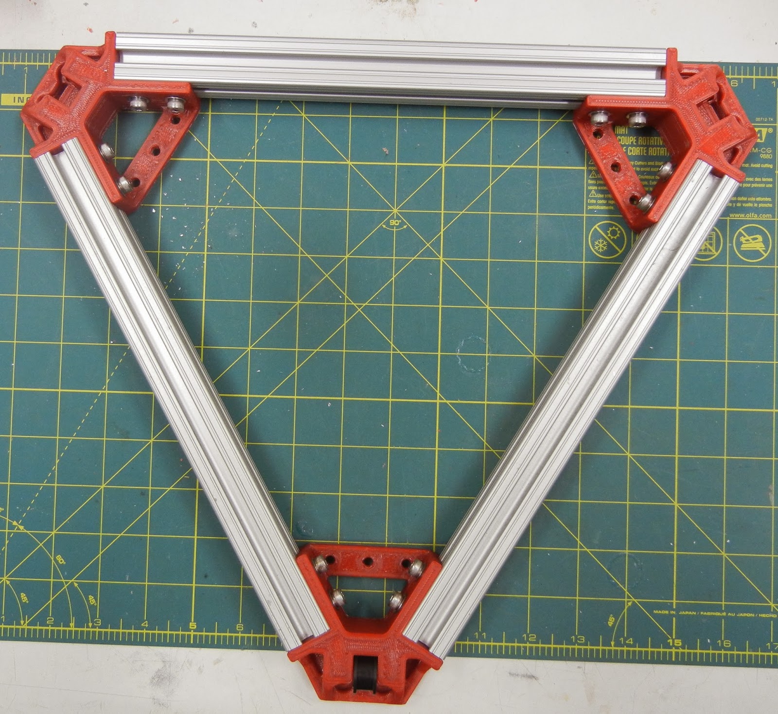
| Upper Triangle Assembled |
 |
| Lower Triangle Assembled |
 |
| Motor & motor mount |
 |
| Testing alignment between upper and lower triangles |
 |
| Testing alignment between upper and lower triangles |
 |
| All 3 Makerslide tower sections clamped together before a final trim to get all three lengths exactly the same |
 |
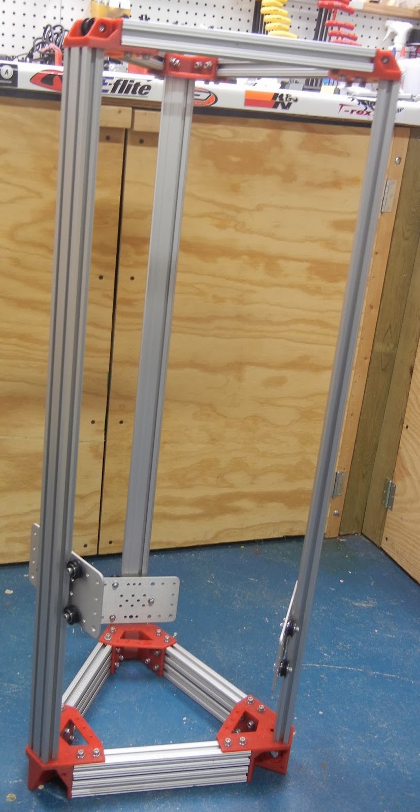
| Frame Assembled! |
The assembled frame seems pretty sturdy- I am considering installing diagonal corner braces just to really stiffen it up.
 |
| Carriages in place |
 |
| Carriage detail |
 |
| The is the whole reason for a new design- keeping the belt return path inside of the vertical extrusions- nice clean look |
 |
| Motor mount, GT2 pulley detail |
Next steps:
- design, print and try belt clamps
- source some suitable tie rods & tie rod ends
As for the Tie (effector) Rods, initially I'm going to try using the same dimensions as the benchmark Rostock 3D printer design:
Rod Length: 250mm Eyelet to Eyelet (same as Rostock)
Traxxas 5347 Rod ends x12 (popular online choice for rod ends)


Nice work!! I've 2 Prusa i3 and is thinking about building a delta bot. I am very impressed by the simplicity and cleanness of your design.
ReplyDeleteThanks for your kind words! The files are all up on thingiverse for your reference / use. I just finished the design for the rod mounts and hot-end mount, I'll be posting them on thingiverse shortly.
DeleteHi like your design, what is the build size?
ReplyDeleteIt uses the standard heated build platform, so about 8.5" x 8.5". I built mine with an approximate Z capability of 14".
DeleteI'm looking to build a Makerslide based delta so still checking the options..
ReplyDeleteHow's the stability of your printer given that the maker slide is just screwed to the top of the motor mounts and not through them as in the Wolfstock?
That's a great question. I have yet to actually print anything on the Snowstock- just test moves and some very rough initial calibration. I will say that I'm not satisfied with the stiffness of the structure. The problem is the flexing of the printed corner brackets immediately surrounding the joint location. I'm contemplating whether I should re-design the corner brackets ala Wolfstock or else add an aluminum plate reinforcement on top of the corner brackets between the bracket and the makerslide extrusions. I think a stiffening plate would distribute the bending load over the entire bracket rather than just the interface between the end of the makerslide and the bracket. My gut feeling is that this would totally fix the flexing issue.
Delete