Wednesday, February 27, 2013

Stepper Driver Replacement + Vapor Polishing ABS

New Pololu A4988 Black Edition stepper drivers
I've been having problems with the X and Y axis on my MendelMax 1.5 reprap losing steps. After checking to make sure both axis has free motion, and double checking the power settings, I thought it might be caused by the cheap www.gadgets3d.com A4988 stepper drivers I was using. So, I ordered some genuine Pololu A4988 "Black Edition" drivers directly from www.pololu.com. These do require some minor soldering to attach standard header pins to the circuit board. The "Black Edition" drivers have a thicker copper layer in the PCB to better handle heat dissipation.

Parts as received from Pololu
Stepper Driver & Header pins, ready for action

Cutting Header pins in half with a small side cutter

Header pins pressed into standard breadboard- will hold pins in alignment  during soldering for easy insertion into RAMPS board.
Applying flux to header pins. Note short end of the pins are soldered to board

Applying flux to solder pads on board
Ready for soldering

Finished, soldered product
 I inserted the new boards into the X, Y, and Z axis. Problems.... The Z worked just fine, and stayed cool to the touch. However, the X and Y had issues- part of the way through some sample prints each axis simply stopped working period. I switched back to the original gadgets3d drivers until I can troubleshoot the problem. The new Pololu drivers do run much, much cooler than the gadgets3d drivers.

 Vapor Polishing ABS printed objects
I saw online that some people have been experimenting with vapor polishing printed objects to produce a really nice surface finish. This blog has a great step by step instructions on how to do it.

Polishing example, courtesy of RepRap:Blog

I decided to try this on some parts I printed for my Rep Rap.


LCD bracket, as printed @ 0.2mm layer height


Vapor Polishing - 3mm of acetone in bottom of jar heated to 90 degrees C on hot plate.  
Once the vapor has formed to the height of your part, place your part in the jar on top of some sort of removable support. Be very careful with this- it can be a fire / explosion hazard and the acetone vapors are a health hazard. Leave it in as long as you want, you can visually see the part smoothing out. Remove the part, and let sit until cured.

Vapor condensate layer visible on glass. Part was left in beaker for about 15 minutes
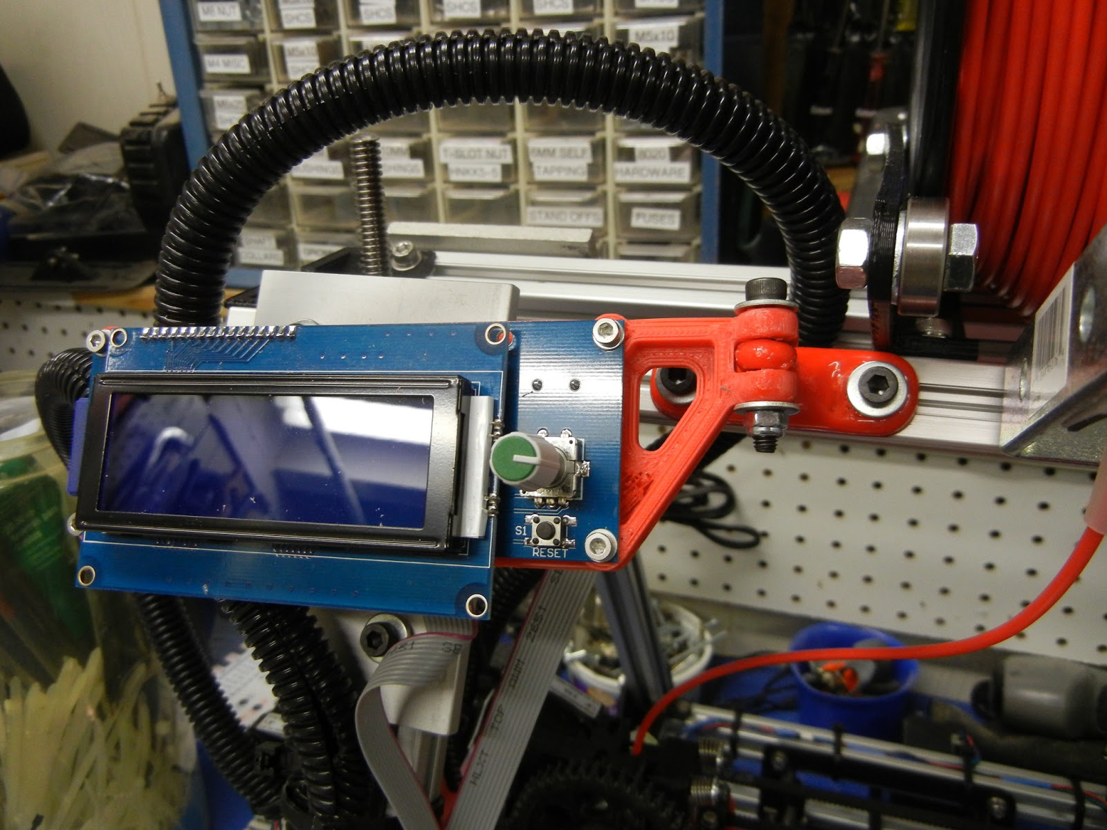
Finished, Polished par.t Be sure to allow the part to fully cure- all the acetone to evaporate out of the part. It may be possible to bake out the part at a low temperature to speed the process. The finished part has a glassy sheen.
LCD screen mounted on MendelMax. I'll upload this to www.thingiverse.com when I have the design a bit more polished.

Thursday, February 14, 2013

Quick Update

I've been spending a lot of time trying to get the rep rap mendelmax tuned. I'll be posting some photos later, but here is a quick summary of what I've learned:


1) X and Y axis losing steps- I spent a bunch of time tweaking the pots on the stepper drives, and couldn't totally eliminate the problem. I'd get 1/2 way through a print, and it would lose some steps and ruin the print. Eventually I tried reducing the x/y "jerk" setting in the Marlin firmware, as suggested by some people on the mendelmax google group. That seemed to work pretty well.
2) tangling of the filament jamming up the system - I printed out a cool filament spool holder right after I was able to get the printer running. For the most part it worked ok, but I was getting random tangles where a few wraps of filament would come off the spool and get tangled with something, jam up the X axis, and cause a lot of missed steps, thus ruining the print. Right now I've stopped using the overhead spool mount (currently shown in the photos in earlier blog postings) and I have the spool off to the side of the printer on a dowel. I think I'm going to rig up something with a guide tube to keep the filament under control so I can go back to using the overhead spool mount.
3) filament feed problems into the extruder- I've learned that your extruder MUST keep the filament properly aligned with the hobbed bolt, otherwise the filament will slowly drift off to the side and stop feeding properly. I ended up putting a couple guide pins into the extruder idler piece to do this. I also was able to order some M3 x 50mm SHCS so I could use springs to keep an even compression on the idler, rather than just cranking down the screws. 
4) 1st layer adhesion- I'm using "abs juice"- ABS dissolved in acetone - painted onto the glass build plate. That works pretty well to keep the first layer stuck down during the print. This, in conjunction with a 100 or 110 degree C build plate works OK. I'm still getting a little lift / warping at the ends of large parts. I've also used blue painter's tape with the hot bed. This seems to work OK for small parts (1" or 2" on a side max), but parts any larger tend to warp and pop off before the print completes.
5) z-lift- enable the z-lift between moves on your slicer- I'm using a 1mm lift- this helps reduce breaking the part off the build platform during prints. 

Wednesday, February 6, 2013

First 3D printed bike project

My first home-made bike part on the 3D printer- a rear light mount for my Surly Big Dummy. When I have the baby seat mounted on the back of the bike, my rear flasher is blocked. That's obviously not safe- so I wanted to make a mount that was super solid, wouldn't be blocked by the baby seat, and wouldn't get in the way of any of the bike's cargo capabilities.

I designed the parts using Solidworks 2012, and printed them on my rep rap Mendelmax 1.5. 

Printing the clamps

Stock mount and light on top, new mount on the bottom

Light mounted on the new clamp mount


Mounted to the bike and ready to go

MendelMax 1.5 Build Log: Part 8, Fixing Extruder

I'm using one of the Greg's Wade Extruder variants, and the small tabs that were meant to keep the filament in alignment with the hobbed bolt broke off. Initially I just used a small piece of plastic jammed into the extruder to keep the filament in line, but that proved to be unreliable. (surprise, surprise) Rather than print out a new extruder idler, I decided to simply drill and tap a hole to mount a 2/56 SHCS as an guide.

Drilling hole for 2/56 screw (0.075" approximate)

Screw Mounted
The screw guide worked great, and totally solved the issues I was having with the filament slipping off of the hobbed bolt and causing a print to fail.

MendelMax 1.5, spool holder mounted and wires cleaned up


Saturday, February 2, 2013

MendelMax 1.5 Build Log: Part 7, Calibration and 1st print


I finally was able to do my initial calibration and 1st print last night:

All axis test

5mm Step Test Object


Before I finally was able to get the machine running, I spent a lot of time trying to track down some gremlins with the non-functional Z-axis. I was having all kinds of problems getting my Z-axis to work, then I tested the cables and discovered that the stepper motor cables had incorrectly attached connectors- no continuity on one of the leads. I cut off the connectors that came with the electronics kit and soldered some home-made connectors on (made from 0.100" space headers).

0.100" Headers

Finished Home-Made Stepper Motor Connector

 That helped a bit- but the Z axis still didn't want to move. I disconnected the lead screws to see if the gantry was jammed, and that wasn't it. Next, I removed the stepper driver board for the Z-axis and swapped it with the extra driver board the kit came with for a 2nd extruder. That was it- not only did the kit I purchased have 4 bad cables (2 stepper, 2 endstop), one of the 5 stepper drivers was bad. Anyway, all axis seem to work great now. Hopefully the electronics kit manufacturer will replace the faulty parts, but as they are our of Hong Kong I don't have much hope. FYI the Hong Kong source was www.gadgets3d.com, purchased through e-bay. Maybe cheap electronics directly from China isn't exactly "inexpensive" after all- just "cheap."

Faulty A4988 Stepper Driver

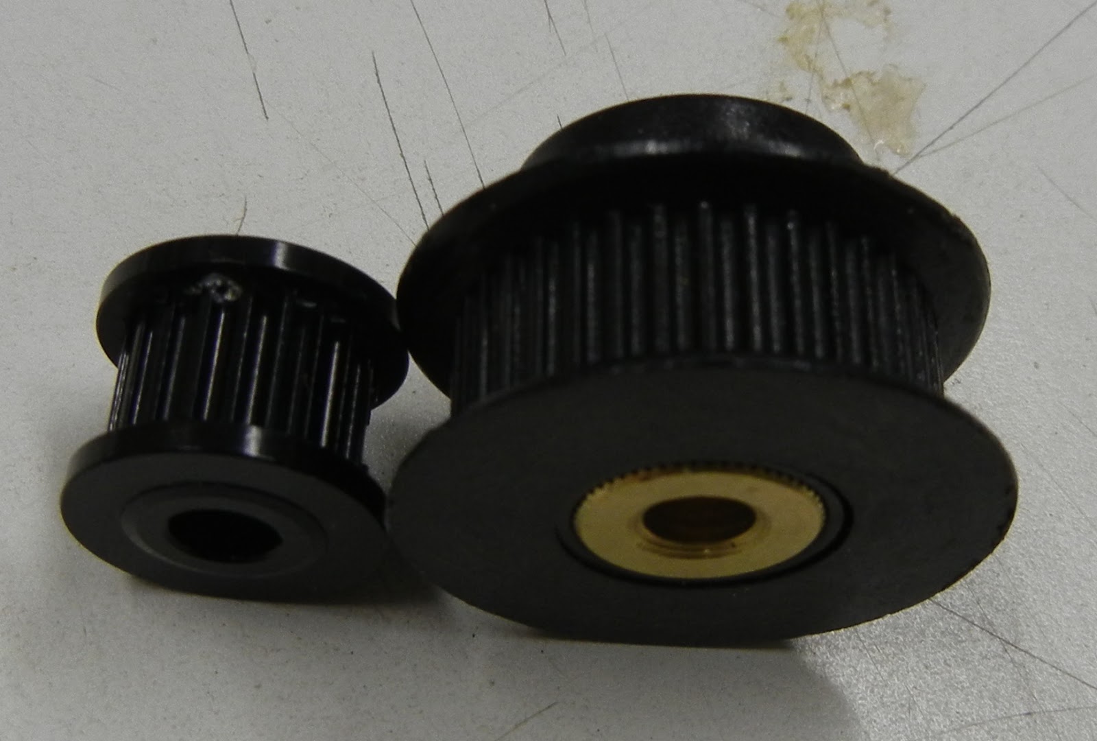
I also swapped out my original larger diameter X and Y axis belt pulleys for some smaller diameter pulleys to increase available torque. The steppers are certainly fast enough so I don't need the larger diameter for belt speed.

GT2 Pulley Comparison

Old, larger diameter GT2 pulley

New, Smaller diameter GT2 Pulley


Now, just to get the print quality dialed in. The build platform is only getting to 70 degrees C- it doesn't want to hit the 110C set point. I think the power supply doesn't have enough capacity to drive all the steppers, the nozzle, and the heated bed at the same time.

I recalibrated the extruder stepper- and that seemed to really improve part quality. The stock settings was pushing too much polymer through the extruder, causing the part to puff up like a marshmallow in a microwave. 

I found an excellent calculator online to assist in calibrating your steppers- very easy to use and fast. mendelmax.com/RepRapCalculator.html.

I ended up with these settings for the Marlin firmware after several rounds of tweaking: (contained in the configuration.h file)

The highlighted numbers below correspond to steps per mm of travel, in the following order, X-axis, Y-axis, Z-axis, extruder

I have not tried playing around the with max feedrate or acceleration values yet.

// default settings

#define DEFAULT_AXIS_STEPS_PER_UNIT   {79.9392,80.3409,1507.3528,680.6504}
#define DEFAULT_MAX_FEEDRATE          {500, 500, 5, 20}    // (mm/sec)   
#define DEFAULT_MAX_ACCELERATION      {900,900,80,10000}    // X, Y, Z, E maximum start speed for accelerated moves. E default values are good for skeinforge 40+, for older versions raise them a lot.


MendelMax 1.5 RepRap ready for action

Frog Model test print- off of Thingiverse

Printing a Spool Holder off Thingiverse

Added Cooling Fan to the RAMPS 1.4 Electronics- this actually seemed to help increase the print bed temperature!

My own design Z-axis endstop holder, now available on Thingiverse for download

 I ended up designing yet another Z-axis endstop holder. My original was too flimsy and didn't work well. My new design is a lot sturdier. I might update the adjustment screw holder again just to stiffen the assembly up even more.

Now that the 3D printer is up and running, it's time to print.... more parts for the printer:

  • ultipanel LCD controller mount
  • cable chains for the X and Z axis
  • fan mount to cool parts being printed

Saturday, January 26, 2013

MendelMax 1.5 Build Log: Part 6, First Light!

Finally, I was able to get the MendelMax Reprap wired up and connected to a PC.

Steps along the way:

I went with 1/2" MDF to mount the heat bed

I drew a simple pattern- I wanted clearance for glass hold down clips, and the center cutout for the termistor


1/2" MDF Cut to shape

MDF Mounted to Y-Axis Slide
Zoom-in detail of  MDF mount on Y-Axis slide
The 1/2" MDF is attached to the Y-Slide using 4x M5 SHCS. The bed can be leveled by alternately tightening and loosening the screws. The way it's mounted it's rigidly affixed. I think as soon as I have the printer running I'm going to update it to add some spring mounts- so the bed can move if there is a head crash.

At this point I could do a very initial bed leveling by manually moving the X and Y axis to make sure the extruder head did not change height over the build plane. I did have to do some adjustments to the bed to get it as level as possible. I'll have to very carefully repeat this step once the machine is functional.

Next, I soldered the power connections and thermistor wires for the hot bed, and screwed it to the MDF.

RAMPS 1.4 board from Gadgets3D.com attached to frame using bracket off of Thingiverse.com


Everything Wired up Prior to tidying up the wires. Note the sweet cable chain on the Y axis also downloaded from Thingiverse (and printed on another printer) Once this printer is running I'll make similar cable chains for the X and Z axis.

Wires Cleaned up, Power Supply Attached (but not plugged in) and Arduino powered over USB

Gadgets3D.com LCD- showing no firmware yet loaded onto RAMPS / Arduino
After everything wired, cleaned up, and ready for first power- I gingerly plugged the USB cable from the Arduino to my old laptop. I didn't plug in the big 12V powersupply that provides the motivation for the steppers and heaters yet, I wanted to make sure all was well with the firmware first. No sparks or smoke- a good first sign.

I downloaded and installed the latest Arduino development environment, and installed the Arduino Mega 2560 drivers. Then, I downloaded the latest Marlin firmware from here.

I did an initial brush through the configuration file before I uploaded the firmware. Since I wasn't really sure of what initial settings are best, I used the recommended settings from the reprap mendelmax configuration page. I also used the modifications for the Gadgets3D LCD panel, described here.

After that, I saved, held my breath, and clicked on the compile/upload button. A minute or two later the LCD panel magically started showing a menu and current updates on the printer!


I downloaded what I've read to be the easiest to use printer interface- pronterface - from this location. I fired it up- and after I entered the correct COM port and Baud rate, it immediately recognized the RAMPS board. Bam. Then, I really held my breath and plugged in the big power supply. Amazingly, no sparks or smoke again. 2 for 2. I initially wanted just to test moving the various axis- unfortunately this is where I hit my first roadblock. I hit the button to manually drive the X axis, and immediately the error came up on both the LCD screen and the PC that the X endstop was hit, eventhough it clearly was not. I believe I need to re-examine how I wired all the endstops (NC or NO), plus whether or not I need a pull-up or pull-down resistor on each on. That'll be the story for another night. In the mean time it's exciting enough just to have it mechanically complete, preliminary wiring down, firmware onboard, and it being recognized by the host computer. Big progress!


Thursday, January 17, 2013

MendelMax 1.5 Build Log: Part 5, Endstop Switches

Before I dove into mounting the endstop switches on my rep rap Mendelmax 1.5, I took the opportunity to salvage a 12v fan and power supply plug out of a dead PC power supply scavenged from my office's technology junk pile.


The power socket on the left will make adding a plug to my 12V power supply neat. The fan will probably be used to either cool the RAMPS electronics or be used on the X-axis slide to cool down the extruded material.

Next up was the mounting of the extruder to the X-axis slide. I didn't have the right M4 SHCS for the job, so I headed over to Lowe's. Being a standard hardware store, they didn't have a huge supply of metric hardware. But, they did have these M4 x 20 hex head screws, which actually worked perfectly.


M4 x 20 hex head screw inserted into the base of the extruder
Extruder and hot-end finally bolted to the X-axis slide!
Now it feels like I'm making some progress! The extruder and hot end are the heart and soul of the 3D printer. The RAMPS setup is the brain but I won't get into that in this post.

Lookin' good

Next on the list- mounting the endstop switches. Every 3D printer has at least 3 endstop switches. One for each axis- X, Y, and Z- and during startup, the machine moves each axis to zero by moving the components until the endstop is triggered. This calibrates the machine and could correct for any drift in the steppers or movement when the machine is turned off. The "stock" endstop mounts are a bit cheezy, and I wasn't able to find anything "just right" on Thingiverse. Luckily we now have a Afinia 3D printer at work, so I was able to design and print new Y and Z axis endstop mounts. I ended up using the stock X axis mount, at least for now.

First, the Z-axis. The X-end mount (in red in the photo below) already had holes in it for the Z-axis mechanical endstop switch. These holes were the right size for a set of 2/56 SHCSs. But, there was no good way to attach anything for the switch to act against. I also wanted this endstop to be easily adjustable- this stop is particularly critical because it will allow for precision adjustment of the extruder nozzle over the print bed.

Z-axis switch mounted
I noticed that the Z-axis motor mount support would be a great place to put a threaded hole- if it were only a bit wider. So I drew up a new bracket, printed it up on the Afinia, and vola. One adjustable mount perfectly positioned. I placed the files on Thingiverse.com if anyone is interested in doing the same.

New Z-axis motor mount with integral Z-axis stop

Z-axis endstop switch, actuated
Next, the Y-axis. I chose to build a framed-in Y-axis slide using Bosch 80/20 style aluminum extrusions. This was easy and made a very stiff and solid Y-axis slide. It also provided a great place to put a endstop.

Front Right corner of the Y-axis slide, showing 90 degree bracket to be used as adjustable Y-axis endstop
I designed and printed a switch bracket that put the switch in the right place. To finely adjust the endstop location, you can move either the switch bracket or the 90 degree bracket attached to the Y-axis slide, whichever is easier. The files for this part are also now on Thingiverse.

Y-Axis switch bracket

Y-Axis switch bracket

Y-Axis endstop switch and bracket installed

Y-axis bracket & switch installed, showing endstop activation

30,000 foot view of the completed Y-axis
The mechanical assembly of the 3D printer is basically complete.There is the matter of construction the build platform, but that should be pretty simple- just a sheet of MDF or plywood on top of the Y-axis slide, and a sheet of glass cut to size.

Now into the unknown- wiring, programming, and setup of the RAMPS controller. Maybe first movement this coming weekend?