Friday, January 3, 2014

Delta Bot Build: Part #2 Belt Tensioners

After initially assembling the frame and trying my first belt tensioner design, I realized that putting the belt tensioners on the moving carriages just clutters up the design and adds additional mass to moving parts. I decided to move the tensioners to the top of the towers instead.

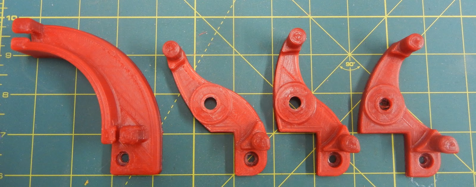
After searching through thingiverse for examples of rostock / delta bot 3D printer belt tensioners, I initially considered mounting the belt idler wheels on an arm that could rotate and thus tension the belt, but as the idler would move in an arc, the belt would possibly rub against the side of the idler mount. Instead of trying to concoct a four-bar linkage that would keep the idler moving in a straight line up and down, I went with a much simpler concept. The idler will be mounted on a plaftform that is moved up and down with three screws, thus tensioning the belt.

All parts are printed with a 0.5mm nozzle, 0.5mm layer height, and 50% fill density. I chose the big nozzle and layer height to maximize part strength. I think fewer layers = better strength, less chance of delamination.

Idler carriage printed and assembled

bottom view- note M5 captive nuts pressed into place

New upper corner bracket installed and belt fed through, ready for idler carriage

idler carriage in place and ready for tensioning


Successfully tensioned!
It seems like this concept works- so I just started printing another set. Hopefully I'll have enough red to finish, this spool is just about finished.

Wednesday, January 1, 2014

Improved filament guide, part 2

I'm a little obsessed with making the filament feed system on my MendelMax as perfect as possible. I've had lots of problems with tangled filaments in the past, and it seems as though a lower-friction feed system should also improve part quality.  The last round of improvements helped, but there were still a couple places where the filament was exposed to sliding friction. I have a bunch of big parts I'm printing for the new delta robot build, and I want to eliminate problems before I waste a lot of filament printing junk.

So, I decided to go crazy with 608 sealed bearings- they are cheap, and I have a bunch left over from the original MendelMax build. I replaced the right-hand side guide post on the upper guide with a bearing, and created a new lower guide with two bearings.

New upper filament guide

New lower filament guide
So far the new guides seem to work great. No tangles yet, and I'm printing a new set of parts for the delta robot build right now.

I posted the files on Thingiverse: http://www.thingiverse.com/thing:199104

Sunday, December 29, 2013

Delta Bot Build

The first time I saw video of a delta robot style 3D printer, I decided the next printer I built was going to be a delta. Based on everything I've learned from my MendelMax, I knew I wanted a printer that was as stout and stiff structurally as possible, with a GT2 belt drive. Some of the deltas use spectra fishing line, which to me seems like a troublesome way to drive the mechanism, particularly since the GT2 belts are so reliable. 

I decided to try using the Makerslide system for the linear bearings vs. the traditional Rostock bearing rods. This solution seems like a nice way to combine a linear slide with the vertical structural components at an affordable price. I sourced the Makerslide linear slide extrusions and related hardware from Inventables.com. 

The Wolfstock style delta-bot seems like a good design. But, I wanted to run the drive belts through the inside of the Makerslide for a cleaner look. I couldn't find quite what I was looking for on Thingiverse, so I started to design my own version. 

All of the solid models are my design work, but they are almost all heavily based on the Wolfstock, Kossel, and Rostock printer designs. I'm putting the solid models and .stl files on Thingiverse if you'd like to download them: http://www.thingiverse.com/thing:214848 This being Minnesota in the winter- I decided to call it the "Snowstock Delta Bot."

The parts from Inventables arrived quickly and all seem to be top quality. I'll definitely keep this stuff in mind for future projects- maybe even some light-duty industrial automation. It certainly is much less expensive than traditional linear bearings.

Linear slide carriage components from Inventables
Laying out the parts for the V-grove rollers
Pressed in one bearing and a M5x20mm SHCS
Using washer to space bearings (so when tightened, compression load is transmitted through bearing hub)
Second bearing pressed in to place
Spacer washer in place

Linear slide carriage assembled
Carriage mounted to Makerslide extrusion

Eccentric spacer allows for adjusting preload of V-grove wheels against Makerslide rail


The overall design of the printer is intended to keep the structure as simple and solid as possible. Some of the other designs I've seen on Thingiverse have really large printed parts. I tried to keep the printed parts as small as possible, and utilize more 8020 style extruded pieces. Really large printed parts take excessive amounts of time to print, and I always have problems with part warp-age or other quality problems. Plus, if you can source the 8020 extrusions used from a industrial surplus source it's really pretty inexpensive.

I printed all of the big structural parts using a 0.5mm nozzle with a 0.5mm layer height. I think the thicker layers are stronger than thinner- fewer opportunities for layer separation.
Base components, one motor mounted to test hole alignment

Base components
Top corners, including idler pulley mount

M5x10mm SHCS, washers, & T-slot nuts ready for assembly
 The first two extrusions are easy to install- locate the screws & T-slot nuts in the printed corners, line everything up, and carefully slide the extrusion into place. The last extrusion is much tricker to install!

Upper Triangle Assembled

Lower Triangle Assembled

Motor & motor mount

Testing alignment between upper and lower triangles

Testing alignment between upper and lower triangles

All 3 Makerslide tower sections clamped together before a final trim to get all three lengths exactly the same

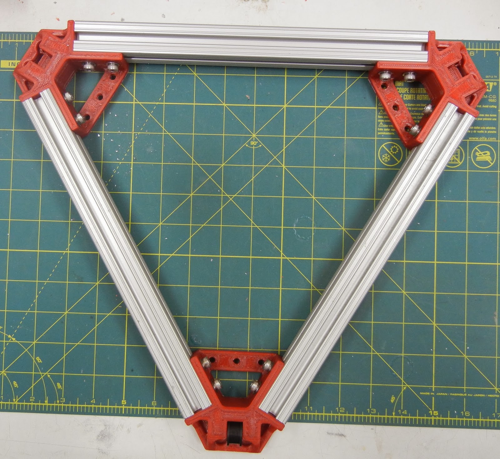
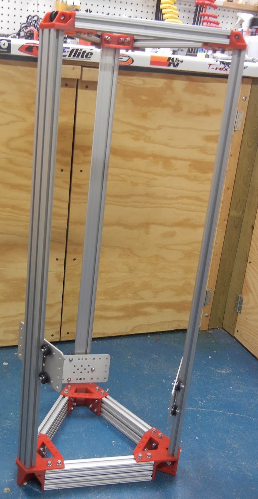
Frame Assembled!


The assembled frame seems pretty sturdy- I am considering installing diagonal corner braces just to really stiffen it up.

Carriages in place

Carriage detail

The is the whole reason for a new design- keeping the belt return path inside of the vertical extrusions- nice clean look

Motor mount, GT2 pulley detail

Next steps: 

  • design, print and try belt clamps
  • source some suitable tie rods & tie rod ends
As for the Tie (effector) Rods, initially I'm going to try using the same dimensions as the benchmark Rostock 3D printer design:


  • Rod Length: 250mm Eyelet to Eyelet (same as Rostock)
  • Traxxas 5347 Rod ends x12 (popular online choice for rod ends)
  • Thursday, December 26, 2013

    Improved Filament Guide

    More efforts to improve filament feeding into the printer- mostly to try and eliminate filament jams around the spool, but also to reduce the force required to pull filament off the spool. The files for this filament feeder can be found on thingiverse: http://www.thingiverse.com/thing:199104

    Components printed and ready to go
    608 bearings pressed into place
    whole range of parts tried- no wheel version on the left, and various guide peg locations on the right. 

    Assembled

    And running!


    Saturday, November 16, 2013

    Terawatt Industries 00str00der Follow-up review

    After running the Terawatt Industries 00str00der for a few weeks, I had a few initial impressions:
    • belt drive extruders seem to be far superior to geared extruders - no backlash, smooth operation, and no wear. 
    • The 00str00der design didn't seem to be optimum, at least for my installation on a MendelMax 1.5 printer:
      • The mounting orientation perpendicular to the X-slides causes considerable flexing of the slide rods during prints, causing the nozzle to move in the "y" direction and thus adding print inaccuracies
      Photo showing stepper motor hanging over front edge of X-slide rods
      • Extruder design doesn't tie stepper mount to structure surrounding hobbed bolt, possibly allowing flex
      • Use of rubber discs for springs vs. wound steel springs does not create as much clamping force between the idler bearing and the hobbed bolt, causing filament feed problems
      • The slots that provide for belt tensioning don't have enough travel, making installation of the belt difficult.
    Since I'm trying to slowly increase the print quality and precision of the printer, I decided to re-design the printer to try and address the problems I noticed. I couldn't find Solidworks files of either the 00str00der or any of the Greg's Wade style extruders, I started this design from scratch, using a few of the existing components. (Idler being one)

    Main features of this new extruder:
    • orients all components directly over X-slide rods to minimize twisting
    • long slots for belt tension adjustment and easy belt installation
    • super-beefy construction to minimize flex within part during prints
    I've uploaded the .stl files and solidworks models to thingiverse, located here

    Belt Drive Extruder, assembled

    Extruder, Mounted

    Note stepper mount is directly attached to extruder body, no gaps
    So far is seems to work well. I did switch the rubber elastomer pucks in the idler tension mechanism for some coil springs. The pucks wouldn't supply consistent pressure on the idler wheel. 

    Saturday, October 19, 2013

    Wolftooth Chainring Install & First Impressions

    After last week's Fatbike Adventure ride, my 9:zero:7 needed some serious love. The bike was still covered in mud, and the bottom bracket was making some serious grinding noises. I had some time tonight to attack it, and I decided as long as I had everything apart, it was time to install the Wolftooth components 30T 104BCD chainring.

    These chainrings have the wide/narrow/wide profile to prevent chain drop even without a front deraileur or chain guide. Also, they have a cool chainring design that allows installation of a 30T chainring in the middle position- normally a 32T is the smallest you can go. Not only are these rings cool, they are also made in the USA- specifically Minneapolis. I rarely if ever use the granny, and going to a single small front chainring should work just fine, along with simplifying the bike and saving weight.

    With the cranks off- I could directly inspect the bearings. The non-drive side bearing seemed OK, but the drive side bearing sounded like it was filled with rocks and felt about as smooth. I don't have any spare 6806-2RS bearings laying around. Rather than waiting for new bearings to arrive, I popped the seal off with a X-acto knife, sprayed it out with some degreaser, let it dry, and packed as much Park Tools grease into the bearings as I could. I kept on rotating the bearing and applying more grease until the grease coming out looked mostly clean. Even after the grease packing they still feel a bit rough. I'll order another set of bearings and install when these start grinding again.

    After the bearings and cups were back into place, I could swap out chainrings, put everything back together, and remove the now-unneeded front deraileur and cables. The chainring install actually turned out to be a big weight savings:

    Added:
    +41g: Wolftooth 30T 104BCD chainring & 4 chainring bolts

    Removed:
    -163g: Shimano XT Front deraileur
    -71g: 32T Chainring, 22T chainring, chainring bolts
    -165g: SRAM X7 front shifter, cables & housing

    Total: 358g weight savings (0.78 pounds)

    It looks great on the bike. Hopefully it works as well on the trails as it looks.

    Installed

    Nice clean look

    Lots of chain clearance- ~ 13mm


    Friday, October 18, 2013

    Magicshine Light + GoPro Mounts

    I've been experimenting with various 3D printed mounts for my Magicshine lights. The stock mount uses a thick O-ring to wrap around the bar- and during rough off-road rides it tends to rotate around the bar. I've prototyped several clamp designs. None of them worked as well as I'd like- once I have a design that works well I'll post it online. 

    In the mean time, after doing last weekend's Fatbike Adventure Ride III, I realized that there are already some really nice helmet mounts for GoPro cameras. Since I wanted to also create an improved helmet mount, it seemed like a great shortcut to making a better mount. It was easy to put together a couple adapters to mount my MagicShine MJ-808 to a GoPro helmet cleat. The adapter uses the LED light's stock 4mm screw to hold it to the light, and the standard GoPro thumbscrews to attach to any standard GoPro mounts.

    MagicShine GoPro adapter, Handlebar / High-Rise

    "High Rise" Adapter with LED light & GoPro helmet cleat

    Side View

    High Rise Mounted On Helmet

    Zoomed View
    My initial mount worked well, but it put the light well above the top of the helmet- sure to get smashed on a low-hanging branch. This mount should work to mount a Magicshine to the GoPro handlebar mount.

    "Low Rise" Mount

    "Low Rise" Mount

    "Low Rise" Mount

    I hope to test the new helmet mount this coming week if the weather cooperates. If it works well, I'll probably post the mount on Thingiverse.