Tuesday, November 6, 2012

FPV Goes Live

"First Light" today on the Q450 quadcopter! I don't have any video available yet because I don't yet have the video recorder. The final steps left before I could fire it up for the first time was simply to mount the camera and video TX on the quad.

Camera Mount

After using a plastic electrical box cover to make the KK2.0 Flight Controller mount, I thought I could find something in the Menards electrical aisle that would work well for a camera mount. Low and behold, a low voltage box looked like it would work great. One low voltage box will make two camera mounts- maybe one FPV camera and one GoPro?

Low voltage box with the trim lines marked


Test Fitting the camera

Test fitting camera after trimming box

Camera Mounted- 2-56 x 1/2" machine screws, lock nuts, and rubber grommets between camera and mount. Hopefully the grommets will act like enough of a shock mount to prevent vibration from shaking camera too much.

Note slot cut in base using dremmel cut-off wheel

Bolted to Hobbyking Q450 quadcopter frame


Video Transmitter (TX) mounted to the "roll cage" using velcro tape and a zip tie


Flight!
So, the big question- how does it work? No video or photos yet... The video quality looks pretty good, but when the motors throttle up there is a fair amount of vibration visible. I'll have to use thicker / softer grommets to isolate the camera better. The camera body might also be touching the orange plastic of the mount- I'll have to grind some material off of the mount to eliminate any possible contact. Other than that, looks great. It was already dark outside so I wasn't able to try any test flights of any distance.

Changing out the old Canon point-and-shoot for the FPV camera and Video TX didn't seem to affect the balance of the quad- no trim adjustments necessary. Adding a GoPro or similar might change the CG more.

I did adjust the camera mount slightly down so it wasn't looking through the rotors. It was very easy to do- just use a small torch to carefully heat the bottom edge of the camera mount, and when the plastic starts getting soft just bend to the desired angle. Not bad for a very cheap DIY FPV camera mount.

Monday, November 5, 2012

FPV- A couple steps closer

So far it seems like getting an FPV quad up in the air consists mostly of soldering a lot of cables together.


Ground Station Progress

Cut Video RX power cable in half, then added an EC3 connector

DC Power plugs for the portable DVD player
I was able to find a great deal on a portable DVD player on Craigslist. This seems to be a great option for a ground station monitor- just make sure it has a video input. The Magnavox I found for $20 has both video input, built-in batteries, and runs off of 9V DC. I removed the battery which dropped the current consumption considerably. Also, so far, it seems like it runs just fine off of a 11.1v 3s LIPO battery. The only annoying thing is that each time you turn on the DVD player, you must manually switch it to video in. Perhaps some surgery on the unit will fix that.....

Another note is that the video RX and DVD player both use 3.5mm 4-pole cables- which are very, very hard to find anywhere locally. These cables look just like headphone cables, but with an additional pole. MCM Electronics has a bunch of very reasonably priced cable options. 

I have a composite video to SD card video recorder on order, also from MCM. This will be very nice for post flight (crash) analysis.

Composite Video to SD Card Converter with AudioMCM Part #: 58-16090  |  Vupoint Solutions Part #: DVC-ST100-VP-BX2


Magnavox portable DVD player (from Craigslist, $20) connected to Video RX (upper center) and power panel (left). See the live video feed on the monitor!
 
Back of power panel. Fuse- to prevent big problems in case of a short. Lighted power switch, and two barrier strips. Below are the power leads for the DVD player and the video RX. There is room on the panel to also add power leads for the upcoming video recorder.

Nice bonus- Video RX + DVD player on only pulls 0.8 amps. (with DVD battery removed) It'll run for plenty of time on standard size 3s LIPOs.

Where to mount the ground station? How about this sweet (and cheap) soft sided suitcase from IKEA!

A couple rivets and velcro should do nicely to hold all the ground station components in place.


Quad-Copter FPV Progress
Camera with wiring harness, before modifications
Video TX, before modification.


Connecting the camera to the video TX couldn't be easier. Connect the camera power leads (red and black) to the power output on the video TX- red and black part of the large group of multi-color wires. Then connect the composite video leads- yellow on the video TX cable bundle, and white on the camera's cable. That's all there is to it. The camera now has power, and the video TX now has a signal. I used some male and female break-away headers from another project to make home-made plugs.

Home-Made connectors using "break away headers" - these were secured together using electrical tape once installed on the aircraft
I'm still trying to get Hobbyking to send me the OSD module that was missing from OSD package. Whenever that shows up (hopefully this year!) it'll also get wired in to the composite video lead. The OSD will provide some very valuable data- namely flight pack voltage and a return to home vector. Both of these pieces of information  will be overlaid on the video that is broadcast to the ground station. Until that is in place I'll have to depend on the low voltage alarm that is currently mounted on the quad. 

Next step, provide power for the video TX. Since this is going to be a very basic FPV setup with limited range and capabilities, I chose to save cost and weight and powered the video system from the main flight battery. A more robust route would be to use an additional battery pack. This particular camera and video TX like 12v DC, so the 11.1v 3s flight pack works just fine.

Added additional JST connector to Quad power distribution board to power the camera and video TX

Camera and Video TX, powered up by the Quad's onboard power
Next steps- build a camera mount. Ideally it'll accommodate the low-resolution FPV camera as well as a second HD camera, eventually a GoPro or similar.

Sunday, October 28, 2012

DIY Automatic Dog Ball Thrower

Sophie, our golden doodle has been even more hyper than usual since our young son has been taking more of our attention. Perhaps there is a way to burn off some of her energy when we are away at work. When we saw a recent issue of Make magazine, (awesome magazine by the way) we knew we had the answer. They had a detailed build of a DIY automatic ball thrower- the "Fetch-O-Matic." I had much of the materials lying around the house so we built an adapted version of the automatic dog toy.

The Make design is a very elegant design. It uses a freely rotating "striker" bar, which is spring loaded. The drive mechanism turns the striker about 180 degrees, loading up the spring. Once the striker rotates past center, the spring rapidly accelerates the striker and brings it back to home position. There is no electronics required, just a simple switch to energize the mechanism when the ball is in the proper location.

The Make version of the ball thrower used a windshield wiper motor. These seem to be rather expensive on E-bay, let alone the local auto parts thrower. We had an old Black & Decker battery powered screwdriver sitting in the junk pile that I thought would work great to drive the device. Tons of torque, works on about 5 volts, and most importantly, free.

I used 3/4" square basswood for both the drive bar and striker. After ten or so ball strikes, the drive bar failed- split along grain lines. I made a new drive bar out of 3/4" plywood and that seems to be quite durable. The drive bar is attached to the motor shaft using a screw threaded into a tapped hole I drilled into the lower shaft collar. I ordered the 7/16" ID shaft collars from Amazon.com, utilizing Amazon Prime free shipping. Without the free shipping I probably would have ordered these from mcmastercarr.com or grainger.com. I used another shaft collar to hold the striker in place.

For power, I used a UBEC from Hobbyking to convert 11.1V from a 3 cell LIPO battery to 5V and to provide low voltage protection for the battery. The lighted on/off switch and ball switch is from Radioshack.

Other than the drive mechanism, the build is very similar to the Make Magazine build. 

Drive mechanism (lower 3/4" square) and striker (upper 3/4" square) attached to motor shaft

Top view of mechanism, upper bar rotates freely about motor shaft, lower is affixed to motor shaft.

Motor Mounted on ball thrower floor

3/4 view of mechanism

I used three small shelf brackets and two hose clamps to mount the motor

Dry Fitting the sides and lower ball guide
Extension Spring- purchased from Lowe's

Spring is mounted- note ball guide and cutout for switch on right side of photo

New Plywood Drive and Switch mounted

Ball wasn't heavy enough to activate the switch, so I added an extension lever cut from 1/8" aluminum

Switch Detail

Switch Detail

Testing the switch- ball held in place with guides. Note there must be clearance for the striker!

Switch Visible

Final, cleaned up wiring on bottom of thrower

"Business End" of the thrower- note the extra ball guides to keep the ball in place

Lighted On/Off switch

Electronics compartment- On/Off switch, UBEC, and 2200 mAh 3s LIPO battery

Completed DIY Automatic Dog Ball Thrower!


Tuesday, October 23, 2012

FPV Camera - fixing connector

For the camera, I chose a 1/3 inch Sony CCD unit, also from Hobbyking. FPV_CCDN


Again, it's a bargain priced unit, but it should do the job at least for my first adventures in FPV. One funny thing about this camera is that the cable socket on the board comes installed incorrectly from the factory- it's reversed. If you plug it in as shipped you run the risk of immediately burning out the camera electronics. Another Q/C FAIL for Hobbyking. The way it's shipped the battery "+" wire is connected to the camera "V-out". Luckily the discussion boards on Hobbyking's website are full of descriptions of how to fix it. Some advocate re-wiring the wire harness, some just to flip the connector on the circuit board. I chose the simple route and just flipped the connector.

Luckily, it's an easy enough fix. Just pull the white cable connector right off the board- gently pry it up or pull straight up if you have strong fingers. It isn't glued to the board. 

Board after connector is pulled off


Then,straighten out the pins the best you can, turn the connector back around, and press it back on. Take extra care to align the pins with the holes in the back of the connector.

Zoomed view showing re-applied connector orientation

Connector re-applied, and cable attached

White = "V-Out", Black = "-", Red = "+"


Cheap OSD for the FPV Quad

I wanted some type of On Screen Display (OSD) for my first try at a FPV aircraft. Knowing your flight pack voltage and direction to home would be very helpful. I just didn't want to spend a ton of money on one.

So, I ordered the Hobbyking G-OSD II.


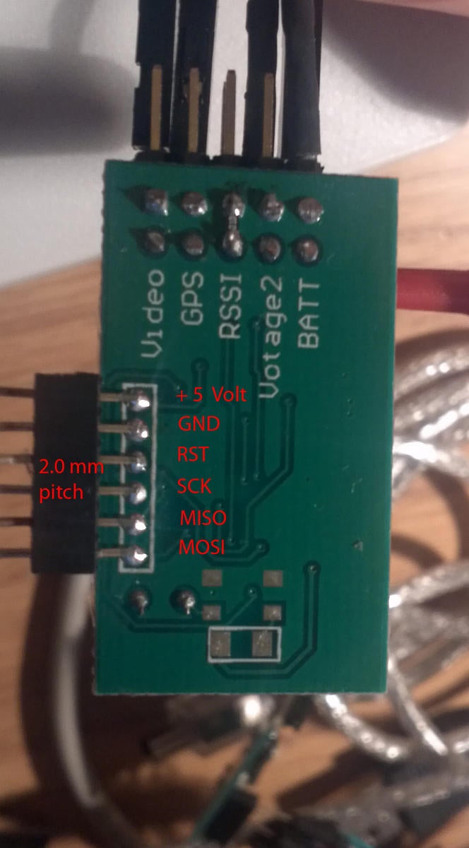
Roughly $40, so not too expensive, and it seemed to have the basic capabilities I was looking for. Plus, there exists a community out there that has some aftermarket software to improve the capabilities. Stock it doesn't have a "return to home" arrow- but the free CL-OSD software does. The trick is that the re-flashing process takes a bit of hacking to do. The G-OSD unit from Hobbyking doesn't come with a pre-installed header to attach your AVR programmer. To get around this, you have to cut off the head shrink and solder your own header in place to a set of small solder pads on the circuit board. I'll find out shortly if my soldering skills are up to the task! 

See SubSonicHobby's post here

And the full CL-OSD page here

Solder Pad labels from CL-OSD wiki
So, I eagerly cut open the package for the G-OSD, and guess what? The actual G-OSD unit is missing! Great Q/C, Hobbyking. The cables, manual, and GPS unit were all there but that's it. Hopefully Hobbyking's customer service will move faster than their usual glacial pace.

Sunday, October 21, 2012

Q450 Quadcopter Flight Videos

The Q450 flies great.... Nice and smooth. I need to tweak the PID settings a bit. It still has a bit of a wobble occasionally, and the auto-level doesn't seem to work, but other than that, great. I think it (and my piloting skills) are ready to start installing the FPV gear.


Friday, October 19, 2012

Q450 Quadcopter Build

The Talon V2 just had too many fussy aspects to it- constant re-alignment of the rotors. So, I decided to sell it to someone who could better appreciate all of its cool carbon fiber and move on to the Turnigy Q450 glass fiber quad frame. It's cheaper, simplier, and doesn't require (or allow!) any sort of alignment. The link below is to the version with the integrated PCB power distribution. For my initial build I used my existing power distribution board instead of the built-in power distribution. I'm also re-using the 18A ESC's and motors from the Turnigy Talon V2 Build, as shown here. Since the Q450 arms were shorter than the Talon's, I was able to cut out quite a bit of extra motor lead length- saving some weight.

I also upgraded to the new KK2.0 flight controller (FC). The FC I used for the Talon had some sort of electrical failure followed by smoke, so it was no longer usable. Luckily I had a new KK2.0 FC on hand waiting to go. I immediately upgraded the KK2.0 to the new v1.2 firmware from the v1.0 it came shipped from Hong Kong with. Find upgrade instructions here.  I never flew it with the v1.0, so I can't comment on if the v1.2 is any better. The new KK2.0 FC is hands down better than the old FC used on the Talon. Much more stability, nearly hands-off hovering, and all around easier to fly- not to mention much, much easier to set up using the built-in LCD display. Definitely worth the extra $15.

Component Qty
Turnigy Q450 glass fiber quad frame 1
Hobbyking KK2.0 LCD Flight Controller 1
Quad-rotor power distribution board 1
Turnigy L2215J-900 Brushless Motor (200w) 4
Hobbyking SS series 18-20A ESC 4

I chose to set up the Quad in "X" mode. Strangely, the pre-drilled holes in the Q450 only support mounting the flight controller in "+" mode orientation, even though the arms are 1/2 white and 1/2 red suggesting that the user fly it in "X" mode. To remedy the situation and allow the flight controller to be properly mounted, I made an adapter plate. Since I didn't have any fiberglass or carbon sheet to make one out of, I used a piece of ABS commonly found at any home improvement store for $0.79 or so- a plastic box cover.

Plastic circular electrical box cover

First, I placed the flight controller over a piece of paper and transferred the four mounting hole locations.  Next, I used a straightedge to trace a line between diagonal holes to find the center. Then I used a compass to construct perpendicular lines to the diagonals I just created. Finally, I rotated the flight controller 45 degrees, lined the new perp. lines up with the mounting holes, then transferred the hole locations. Once the hole locations were set, I used a compass to create an inner and outer circle.

Template taped on box cover

Using this template I drilled each of the mounting screw holes, cut the outside with a bandsaw, and finally cut the center hole with a hole saw. 

Completed adapter plate

Adapter plate attached to Q450 frame with 4/40 SHCSs and 1/2" spacers

KK2.0 FC in place, top view

Note the rubber grommets for vibration absorption above and below the FC board

Since I'm a horrible quad pilot and tend to run into trees, buildings and the ground often, I made a crude roll cage from a piece of 1" wide aluminum and bolted it to the Q450 frame. Crude but effective. It also makes a very nice carrying handle. 

Roll Cage / Carrying Handle  in place

Next steps- lights for night flight and FPV wiring!