Sunday, November 19, 2023

Prusa MK3s+ & MMU3 Upgrade Review

 MMU2s --> MMU3 Upgrade Review

I had an early MMU2, which I later upgraded to a MMU2S. This meant I was using an old 2018 version of the MMU PCB and stepper motor set. The MMU3 upgrade kit doesn't include any of these - it is basically just a hardware kit (as in nuts and bolts), a new power supply board (which is probably the actual critical item of the MMU3), and a full set of redesigned and optimized printed parts (which you print yourself from supplied filament). All of this is well documented elsewhere, so I won't say anything here about the actual build other than it was fairly straightforward and easy to follow. 

MMU control board
Ancient MMU control board- still being used!


Prusa MK3S+ with MMU3
Assembled MMU3 in action

MMU3
Looks familiar but many improvements under the hood

Clown fish printed with MMU3

Clownfish initial test print in eSUN PLA+. Model source HERE

The initial test prints were 'out of the box' better than the old MMU2s - but still not perfect. Interventions were still needed - but a large improvement from the MMU2s. The errors were also much easier to deal with as there is now some trouble-shooting text displayed on the printer's LCD. 

Errors typically were of two types:

  • The FINDA or print head sensor wouldn't recognize the filament change had been successful and reached the head sensor
  • During filament retraction, the filament tip would back too far out of the selector, so the selector couldn't grab and load it during the next exchange

FINDA Tuning

To address the FINDA error described above, I adjusted FINDA sensor. The installation manual recommends setting this to to barely turn on when a filament is inserted - however didn't always recognize when a filament was inserted during changes. I adjusted this to barely turn off when a filament was removed - this seemed to increase reliability of filament changes, in particular with flexible filaments. The new method of tuning this sensor with a screw is a big improvement over the MMU2. 

After adjusting the FINDA- the only failures seen was from filament retracting too far out of the MMU selector- probably due to the auto-rewind spool holder. I'm also printing TPU using the MMU, which seems to work better than expected as this isn't a supported filament type from PRUSA. 

Too much auto-rewind action

I'm using gravity auto-rewind filament spools. These seem to cause intermittent problems by pulling too much filament out of the selector during filament change. I'm planning on switching to a simpler spool holder with no auto-rewind, and just a method to manage the slack created during filament unload. I haven't found an existing design yet that I like, I might just design and build one. 


3D Printing FDM Multi-material adhesion experiment

Background

Most multi-material prints I've seen on Thingiverse or Printables involve using multiple colors of the same material for cosmetic effects - printing characters, making art, etc. 

While this is interesting, being able to print multiple types of filament in the same 3D print also enables using different materials for mechanical design reasons. Examples include adding a soft touch surface to a rigid mechanical part or flexible hinges to a rigid part. 

For this to work, the different materials must adhere together during printing. If there is no bonding during printing, mechanical interlocks could also be used. 

I'm planning on designing and making a part which good adhesion during printing is desired, so I conducted a quick experiment to test adhesion between various materials.

Method

I designed a small block- 25mm x 25mm with two solid bodies. Test block available on thingiverse here

I had 4 material combinations I wanted to test:

  • PLA to TPU
  • PETG to TPU
  • Nylon to TPU
  • PC to TPU
For this experiment, for all experiment trials conducted, the experiment material was the base, printed directly on the build plate, and the TPU was the top material. 

Equipment

  • Prusa Research MK3S+ with MMU3
  • Prusa Research smooth PEI build plate

Prusa Slicer really didn't like using TPU as a material option to print with the MMU, so you need to manually select this material profile in the filament tab.

PLA / TPU test block

All Test blocks


Results Table

Base MaterialTop Material Adhesion
PLA
eSUN PLA+, Blue
TPU
ANYCUBIC A11795 TPU, red
Very Good
PETG
Prusament, Orange
TPU
ANYCUBIC A11795 TPU, red
Good
Nylon
https://www.lay3rs.nl/ Nylon, Black
TPU
ANYCUBIC A11795 TPU, red
Very Poor
PC Blend
Prusament PC Blend, Black
TPU
ANYCUBIC A11795 TPU, red
Poor

Conclusions
This TPU appears to adhere well to both PLA and PETG. Qualitatively, PLA may be slightly better, but both seemed firmly adhered with this test piece.

Tuesday, January 9, 2018

Adding Status LED lights to RE-ARM smoothieboard

I've been the happy owner of a RE-ARM smoothieboard that I purchased through the kickstarter campaign. If you haven't heard of this board, it's a cost-effective way to upgrade your existing 3D printer that uses a Arduino Mega with Ramps 1.4. The RE-ARM replaces the old and creaky 8-bit Arduino Mega with a powerful ARM based Smoothieboard- and keeps your Ramps 1.4. It's basically a plug-and-play upgrade. The software configuration is fairly straightforward, and there are many example configuration files on the smoothieware website. In addition to the improved processing power, it also had a big advantage in configuration- you simply update a config file on the SDCARD and reboot- no recompiling each time you want to change a setting.

It was a great upgrade to my "snowstock" delta printer over it's original Arduino Mega. The old Mega didn't really have enough processing power to drive the delta, resulting in poor print quality and many pauses during print, particularly when it was trying to drive a LCD panel.

All was well until I did a firmware update last week, and something went wrong, apparently "bricking" the re-arm. It wouldn't even show up as an external USB drive when attached to my PC. I asked for help on the forums- and was asked for status lights on the smoothieboard. The re-arm only has one status light- power - so no help there. Another helpful person on the reprap forums described how to add status lights to the re-arm. I added status lights to my re-arm- which told me my firmware was locked up. I ended up downloading a fresh copy of the latest firmware from the smoothieware github site, and that did the trick. The version I downloaded that temporarily bricked the board must have been corrupted.

Example status LED example from Youtube:

Even though they were not helpful for this problem, the status lights do seem like a good thing to have available. I thought it might be helpful to post pictures of what I did. Also a note- the LED's are not in order of the smoothieboard- on this implimentation on the re-arm they are left to right, LED3-LED4-LED2-LED1.

I only have through hole components and supplies. The sample circuit shown on the youtube video linked in the reprap forums uses surface mount components. The build shown below only uses simple through hole components.

"Bricked" RE-ARM, power light illuminated- no other clues about what is going on
RAMPS 1.4. Note the unpopulated servo pins at the bottom center of the photo, immediately to the right of the reset button. This is where the status LED will be installed. 


Step 1: Add female headers to the RAMPS 1.4 board to allow addition / removal of the status LEDs from the RAMPS board. Note we only need to add headers to the ground row and signal row of the servo pins.

Female header pins I had available
Trimming the headers to 4 pins wide


I used a 3x6 male header pin array to keep the proper spacing on the female header when I solder them to the RAMPS 1.4 board. 
Another view of the female headers prepped for soldering


Female headers inserted into the RAMPS board

Female header soldered into place & excess pin length trimmed

Male header pin array removed. The male pin array kept the female headers nicely aligned during soldering onto the RAMPS board.

Supplies Needed
 Step 2: Gather materials needed:

  • 4x 1k ohm resistors
  • male header pins
  • LEDs
  • perf board (I used cheapo non-plated perfboard, but anything would work)
  • breadboard (used to keep pins aligned during soldering)
Step 3: Layout and solder

Cut 2 male header pin strips- 4 pins long, insert into breadboard as shown
Insert 4 1k ohn resistors into perf board

Flip over and place on top of male header pins in breadboard (see tips of male header pins slightly protruding through perf board)

Nicely lay out resistor leads

Solder resistor leads to first row of header pins

Trim & solder long LED lead (anode / +) to second row of header pins- right side of photo. Solder short LED lead (cathode / - ) to left resistor lead. Trim excess leads. 

Completed "dead bug" build. Note the various LED leads have to be sided to space out the LEDs. Also make sure the various LEDs are not shorted to one another. 

Completed board trimmed and ready to go. Ugly(!) but functional. 

Side view

Step 4: Plug into RAMPs

New LED board plugged onto RAMPs. Note LED anode / + connect to the signal lead, and cathode to ground (through 1k resistor to control current)  All LEDs lit- firmware crash!
Step 5: Check LEDs vs. reference
See Smoothieware wiki. Again, note that the LED order on the RAMPs board doesn't match the "real" smoothieboard: left to right, LED3-LED4-LED2-LED1.


Fixed- test print with Benchy


Sunday, September 17, 2017

Arduino controlled 3D Printed Automatic Fish Feeder

Recently I designed & put together a really simple small aquarium automatic fish feeder. The design files & simple build instructions are located on Thingiverse here.


And, since I didn't immediately see an easy way to park code on Thingiverse, the code is below:

/***********************************************************************************
Small fish feeder

code is set to have the feeder run 1x per day. It runs once immediatley upon startup,
then waits 24 hours for next run. For testing comment out the DAY (24*HOUR) line
and uncomment Day (2*SECOND) line
*****************************************************************************************/

#define SECOND 1000L
#define MINUTE (60*SECOND)
#define HOUR (60*MINUTE)
#define DAY (24*HOUR) //uncomment for actual run
//#define DAY (2*SECOND) //test setup

const int SERVO_PIN = 3; //pin number for the led pin - this is 'const' since it will not change during code, and saves Arduino memory
const int FILL_DEGREE=5; //starting hole location, fill slider with fish food
const int DISPENSE_DEGREE=45; //dispensing hole location

Servo servo1;

//setup runs once when the Arduino is turned on
void setup()
{
servo1.attach(SERVO_PIN); //attach the servo on pin SERVO_PIN

} //setup() is done, go to loop()

//loop runs forever once setup is complete
void loop()
{
//******************************************************************************
//NOTE: YOU WILL HAVE TO CHANGE THESE VALUES based on your servo horn alignment.
//******************************************************************************

servo1.write(FILL_DEGREE); // tell servo to go to fill position
delay(1000); // delay for 1 second
servo1.write(DISPENSE_DEGREE); // tell servo to go to dispense location
delay(1000);
servo1.write(FILL_DEGREE); // tell servo to go back to fill position

delay(DAY); // delay for 1 day
}

Tuesday, May 23, 2017

Fixing battery powered air mattress inflator with an Arduino Nano & Lipo batteries

Our rarely used air mattress inflator bit the dust. It's a old Coleman rechargable Quickpump that used a 6 volt lead acid battery. It had two problems. One, the battery was toast and wouldn't accept a charge, even when directly attached to a nice charger. Two, I had lost the charger some time back so even buying a new battery would cause a charging hassle. Instead of buying a plug-in charger which would have been the easier move, I decided to fix it using parts on hand.

Be warned that any dealing with LIPO batteries is potentially risky. Try this at your own risk!

Proposed solution:

  • 2s or 3s LIPO batteries- normally used for drone or RC airplanes. Great power source but a bit risky to use since they do not have any built-in over discharge protection.
  • MOSFET to handle power distribution
  • Arduino Nano- I thought it would be possible to use the Nano to control the system and safely run the pump off of the LIPO using the following strategy:
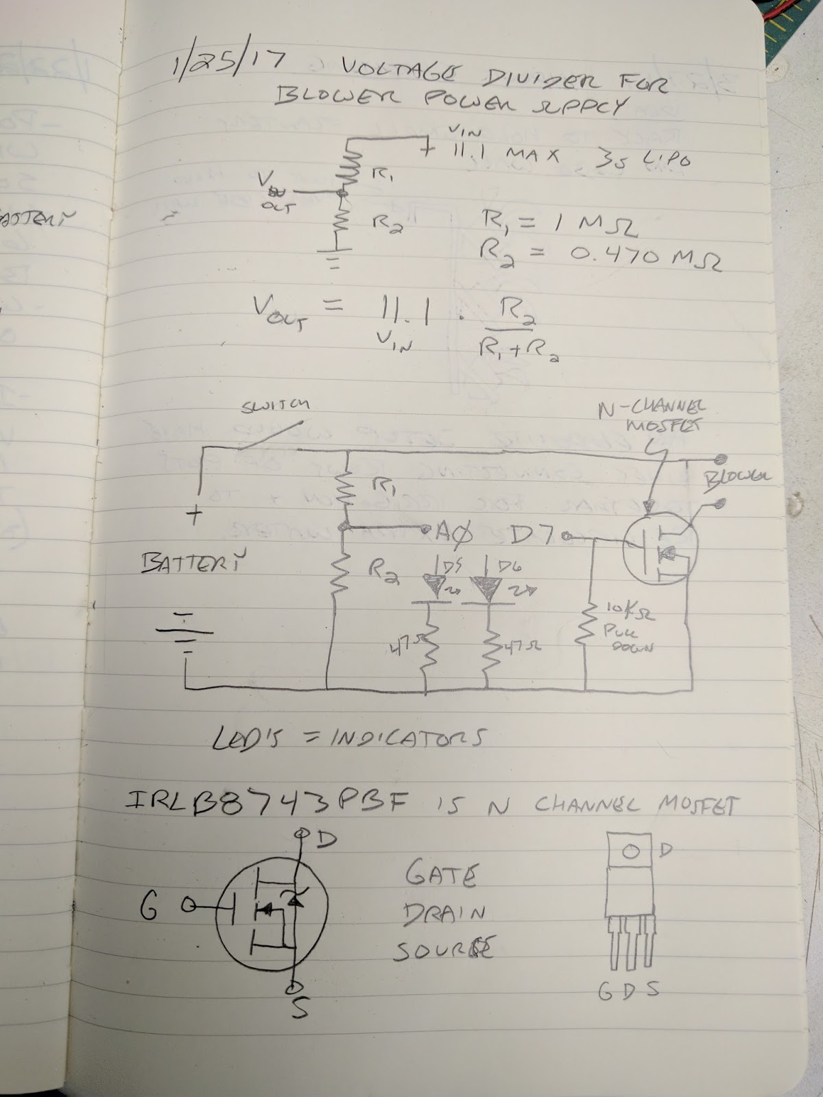
    • using a voltage divider, read the battery voltage and determine if it was a 2s or 3s battery (assuming the use of a LIPO pack)
    • determine if the battery is in a safe operating voltage, and if not, shut the system down
    • PWM the output to simulate a 6V power source for the motor
It's not well tested, and the code is messy, but it seems to work fine. I ended up not using the indicator lights as listed in the schematic and code. They really were not necessary, and they also seemed to make the circuit not work- perhaps I didn't have the pull down resistor sized properly on the MOSFET gate?

Schematic with calculation for voltage divider

There is a specific MOSFET listed, but any MOSFET that is N channel and can handle sufficient current should work. 

I tested the circuit out on a breadboard first. After that seemed to work I soldered it on to a cheap 4x6cm protoboard and installed it in the pump shell. It was a bit of a tight fit on the protoboard. 

Circuit installed in pump shell
The way it actually is wired is with the off/on switch controlling the + output- this way the Arduino will boot as soon as the battery is connected. The downside is that the Arduino will draw power the entire time the battery is connected- which would eventually destroy the LIPO.

Circuit detail

ready to rumble!


Ugly code- note there is a collection of serial print hooks to track what is going on with the code / circuit:

/*
This software allows a 3s or 2s LIPO to power a 6V air mattress inflator

reads input voltage through voltage divider
determines if 2s or 3s battery is attached
if battery is in acceptable voltage range, allows pump to run and turns green LED on
if battery is too low, does not allow pump to run and turns red LED on

utilizes analog output (PWM) to simulate desired output voltage using MOSFET to control higher voltage and current from LIPO battery
 */


void setup() {
  // initialize serial communications at 9600 bps:
  Serial.begin(9600);
}

void loop() {
// constants

int analogInPin = 0;  // Analog input pin that the potentiometer is attached to
int GreenLEDPin = 5; // digital output pin that the green LED is attached to
int RedLEDPin=6; // digital output pin that the red LED is attached to
int MOSFETPin=3; //output pin for MOSFET, must be PWM capable pin
float R1=100; //R1 value of voltage divider (divided by 1000)
float R2=48; //R2 value of voltage divider (divided by 1000)
int Lipocell=0; // default lipo cell count
float mincellV=3.0; //standard low lipo cell voltage
float cell_cutoffV=3.2; // cutoff voltage
float maxcellV=4.2; //standard high lipo cell voltage
float batteryV=0; //battery voltage
float sensorValue=0; 
float inputVoltage=0;
int outputV=6; //voltage desired for output
float outputValue; //value for analog output

//pinMode(MOSFETPin, OUTPUT); //set MOSFETPin as output

  // read the analog in value:
sensorValue = analogRead(analogInPin);

inputVoltage=sensorValue * 0.0049; // 5 volts / 1024 resolution = 0.0049

batteryV=inputVoltage * (R1+R2) / R2 ;

// determine if battery is 2 cell or 3 cell battery or if no battery is connected
if(batteryV >= (mincellV*2) && batteryV <= (maxcellV*2)) Lipocell=2; //set cell count to 2
if(batteryV >= (mincellV*3) && batteryV <= (maxcellV*3)) Lipocell=3; //set cell count to 3
if(batteryV < (mincellV*2) ) Lipocell=0; //set cell count to 0 (no battery)

outputValue = map(outputV, 0, batteryV, 0, 255); // map desired output voltage to PWM & output

// determine if the battery voltage is within acceptable range and battery is present & act accordingly
if(batteryV > (Lipocell * cell_cutoffV) && Lipocell != 0) 
{
  analogWrite(MOSFETPin, outputValue); //start MOSFET using PWM value
  Serial.println("turning on output pin");
  digitalWrite(GreenLEDPin, HIGH); //green light on
  digitalWrite(RedLEDPin, LOW); //red light off
}
else
{
  analogWrite(MOSFETPin, 0); // if battery too low set output to zero
  Serial.println("turning off output pin");
  digitalWrite(GreenLEDPin, LOW); //green light off
  digitalWrite(RedLEDPin, HIGH); //red light on
}

  // print the results to the serial monitor:
  Serial.print("input voltage = ");
  Serial.println(inputVoltage);
  
  Serial.print("battery voltage = ");
  Serial.println(batteryV);

  Serial.print("LIPO cell count = ");
  Serial.println(Lipocell);

  Serial.print("output value=");
  Serial.println(outputValue);

  Serial.println(); //blank line for clarity

  // wait XX milliseconds before the next loop
  
  delay(1000);
}


Sunday, January 8, 2017

Shapeoko2 X-axis beam upgrade & Dinosaur Bookends

The stock Shapeoko2 used two standard makerslide extrusions, separated by a small air gap, for the X-axis linear rail. This worked OK, but the assembly tended to twist and cause inaccuracy or cutting problems when driving the machine too hard. Some people stiffened their machines by bolting the two extrusions together or otherwise tying the two beams together and approximating a single beam.

Inventables recently released a new "Wide Makerslide" for their X-Carve CNC router. This new extrusion replaces both X-axis makerslides in their X-Carve product, and yields a much stiffer X-axis. This new part is a very easy and fast upgrade for older Shapeoko2 machines. They sell it in 500mm, 750mm, and 1000mm to fit most machines. My machine has the narrow X-axis so I needed the 500mm part.

Stock setup on the left, still assembled. New extrusion on the right.
Pay close attention to stepper motor wiring order when disconnecting Y axis steppers to disassemble unit
Together and ready for testing!
Cutting out parts for Dinosaur Bookend for Christmas present
The first project built with the upgraded Shapeoko2 were a set of these cool dinosaur bookends. They turned out great and were a hit at Christmas. The ~0.5" plywood was sourced from Menards- they had a super sale on Christmas Tree bases- pretty nice quality pseudo baltic birch 2' x 2' squares for $1.90. The bookend bases were cut from Ikea bamboo cutting boards.

Finished bookends

Shapeoko 2 Upgrades using XCarve parts

This post is actually a little out of order- I actually did this before rebuilding the Z-axis.

After doing some initial aluminum cutting and also running into some size limitations with the stock Shapeoko2, I decided I need to upgrade the machine to make it both a) larger and b) stiffer.

Inventable's X-Carve has a number of parts that are bolt-on upgrades that are compatible with the Shapeoko 2. The first I purchased was the improved DC Spindle mount. This provided a much-improved interface between the DC spindle and the Z-axis slide- both improved rigidity and alignment. It's machined from a single aluminum extrusion and black anodized.
Spindle Carriage
DC Spindle Mount
The second upgrade I purchased was the X-Carriage Extrusion. This was definitely a huge upgrade over the stock Shapeoko2 X-Carriage. The stock x-carriage is an assembly of plates bolted together with a ton of spacers and washers- it works, but the improved part is one massive extrusion. It should prove to be much stiffer in actual use.
X Carriage Extrusion
X-Carriage Extrusion


Installation of the upgrades was pretty straightforward. The entire Shapeoko2 X axis needs to be disassembled. The wheels and stepper motor can be attached to the X-Carriage. Then, the X-carriage extrusion is slid over the X-axis Makerslide extrusions. 
X-Carriage assembly in process.
Once the X-axis is re-assembled, the Z-axis with the new, improved DC Spindle mount can be bolted on and everything aligned.

I also took the opportunity to expand the stock build surface using new makerslide and some 8020 extrusions I purchased from an industrial salvage place.
Installing electrics on a board attached to the bottom of the frame

New, Super Beefy 8020 Frame, laid out but not yet squared
Just about ready to bolt together
Squared up and bolted together.

I used the stock 500mm x 500mm wasteboard, then added a new wasteboard I cut from 1/2" MDF. I did buy a set of 5mm threaded inserts to add hold downs to the new section.

New wasteboard cut from 1/2" MDF and hole locations marked
Holes cut and M5 threaded inserts added
New Wasteboard & Y axis makerslide braces in place
Assembled and ready for first part- a new faceplate from 1/8" MDF:

Cutting faceplate for E-stop and spindle RPM control
Faceplate cut & spray painted silver
Finished, assembled and ready to go