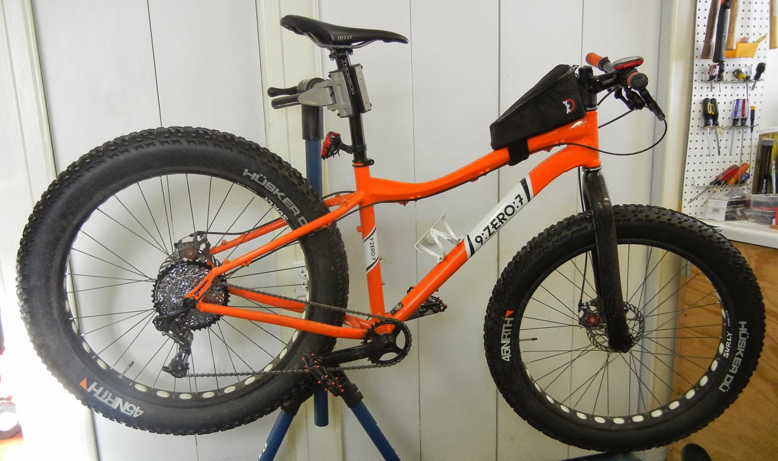
I ditched my 9:zero:7's front deraileur by using a
Wolf Tooth components 30T front cog several months ago. This gave me a lowest possible gear of 30T front, 34T rear- fine most of the time, but for really deep snow or steep climbs I wanted an even lower gear. Since I was originally running 9 speed SRAM components, a 34T rear cog was as big as I could go. When I saw Wolf Tooth was coming out with a 42T rear cog, I got excited- it seemed to be a cost-effective way to simulate SRAM XO1 or X11 without the giant price tag. Essentially it works by adding a new larger 42T cog at the large end of the cassette, and omitting the 17T cog from the cassette's midrange.
There are other companies
(OneUp components being another) making 42T cassette cogs, but Wolf Tooth is a Minneapolis company and besides that, seems to make great quality product. The GC42 seems to be in short supply right now- there must be a pent-up demand for a product like this.
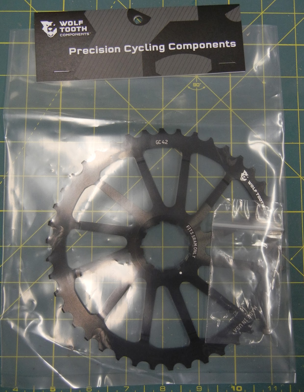 |
| GC42! |
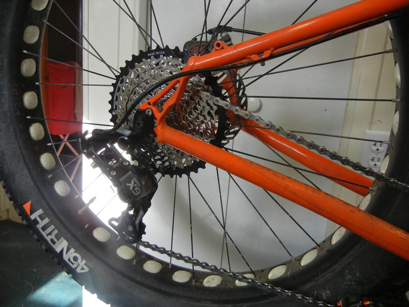
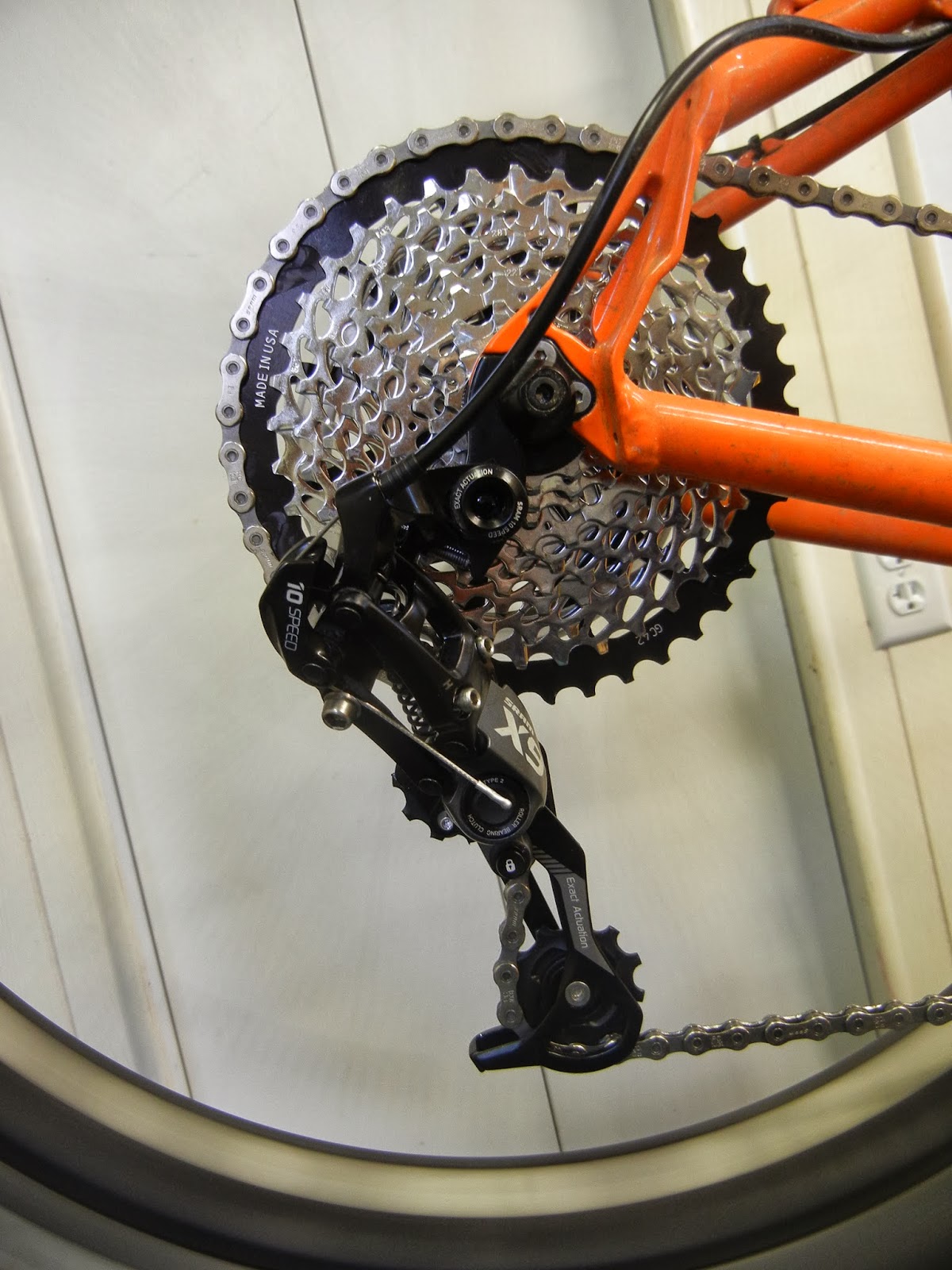
To use the new GC42 I had to convert to 10-speed, though. I went with a SRAM X9 mix for economics- X0 or Shimano XT would have been great options but more money. I'm also excited to move to a Type 2 rear deraileur- no more chainslap- hopefully a totally quiet ride even on rough terrain now.
Exact Components Used:
Extra Components that I found I needed during install:
- extra SRAM 10-speed chain master link
- scrap section of 10-speed chain from other bike to donate a few links
Wolf Tooth has a good set of instructions posted on their website. Of course, I didn't bother reading them until after I finished the install! Note this isn't quite a toss it on and ride kind of upgrade, there was a lot of playing around with the B-screw tension and chain length to get it up and running. Even after 30 minutes or so of adjustments, the upshift from the 36T to the 42T isn't quite perfect. I'm guessing after the first ride it'll improve- I think the 42GC needs to rotate slightly on the freehub body splines to get the upshift ramps and sharktooth cog gears in perfect alignment.
 |
| Before surgery - SRAM X7 9-speed, 34-11 rear cassette |
Installation
Bolting everything on was simple, no different than installing any other deraileur / shifter / cog upgrade. Removing the 17T tooth cog was likewise simple- just make sure to pull out the correct cog and spacer, and get the rest of the cassette stack on the freehub body in the proper orientation.
 |
| I like the "MADE IN USA" label! Not too often you see that on bike parts these days |
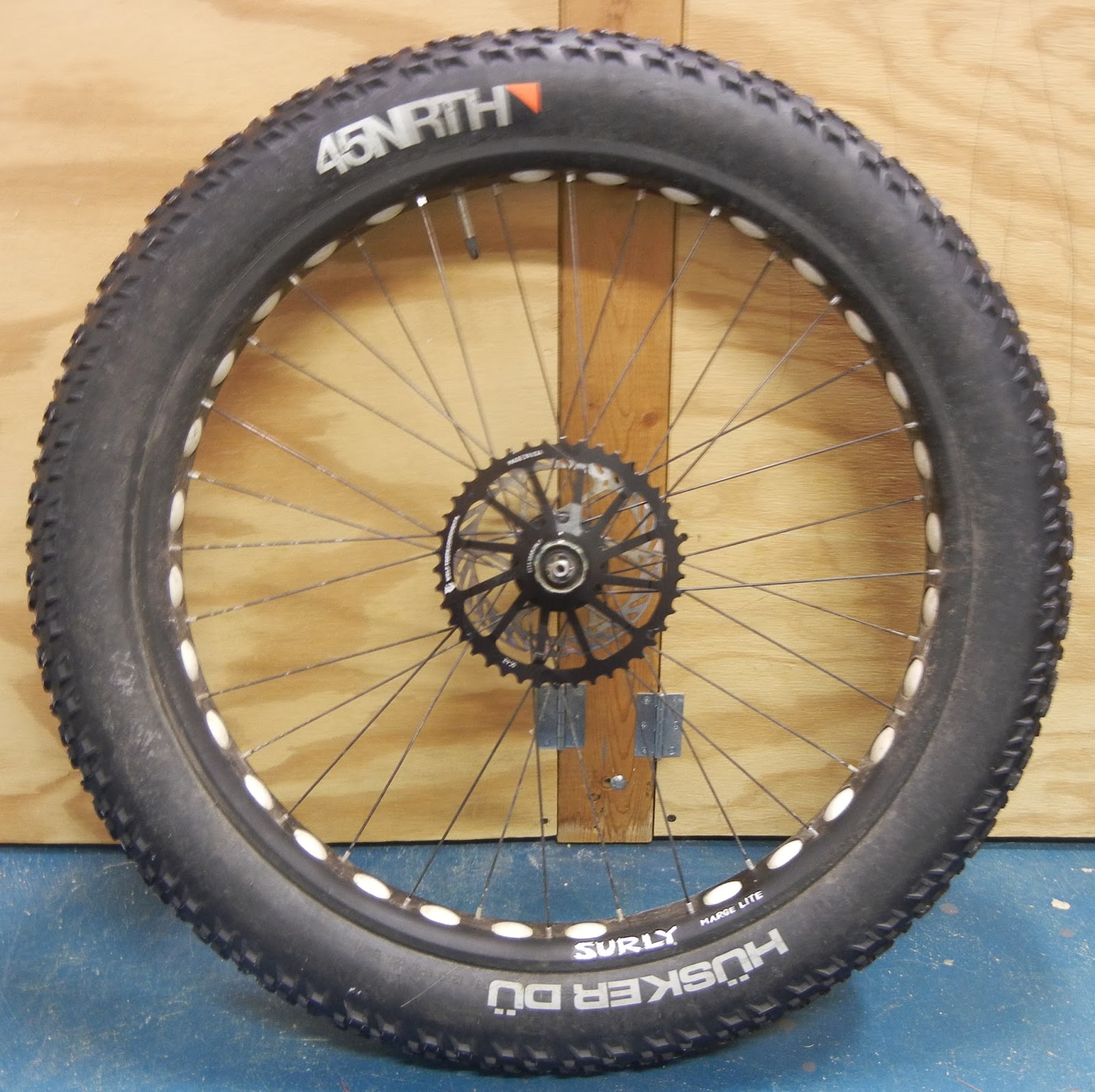 |
| 42T Cog installed on the 9:zero:7 rear hub. |
 |
17T cog and spacer removed from the Cassette stack
 |
| Everything slid into place and locked |
|
 |
Ready for tuning
 |
I originally tried to use just the full brand new PC1031 chain (114 links) but it wasn't long enough- very scary trying to upshift into the 42T on the stand, total lock-up. I tried maxing out the stock SRAM B-screw tension, then added the Wolf Tooth longer B screw- still not enough to get the derailleur to shift into the 42T. (note the Wolf Tooth longer B screw wasn't actually necessary)
Next step, longer chain. I had some 10-speed Dura-Ace links in my toolbox- I added about 10 links along with an extra SRAM master link to tie it all together. That was much too long- the derailleur didn't have enough capacity to tension the chain while in the smallest cog. So, I started to remove links and re-assemble until I had a chain length that would shift into the 42T while still having some tension left while in the 11T cog. See the picture below for how much chain was needed- depending upon how you count chain links, about 4 pin to pin distances added including the new Master Link.
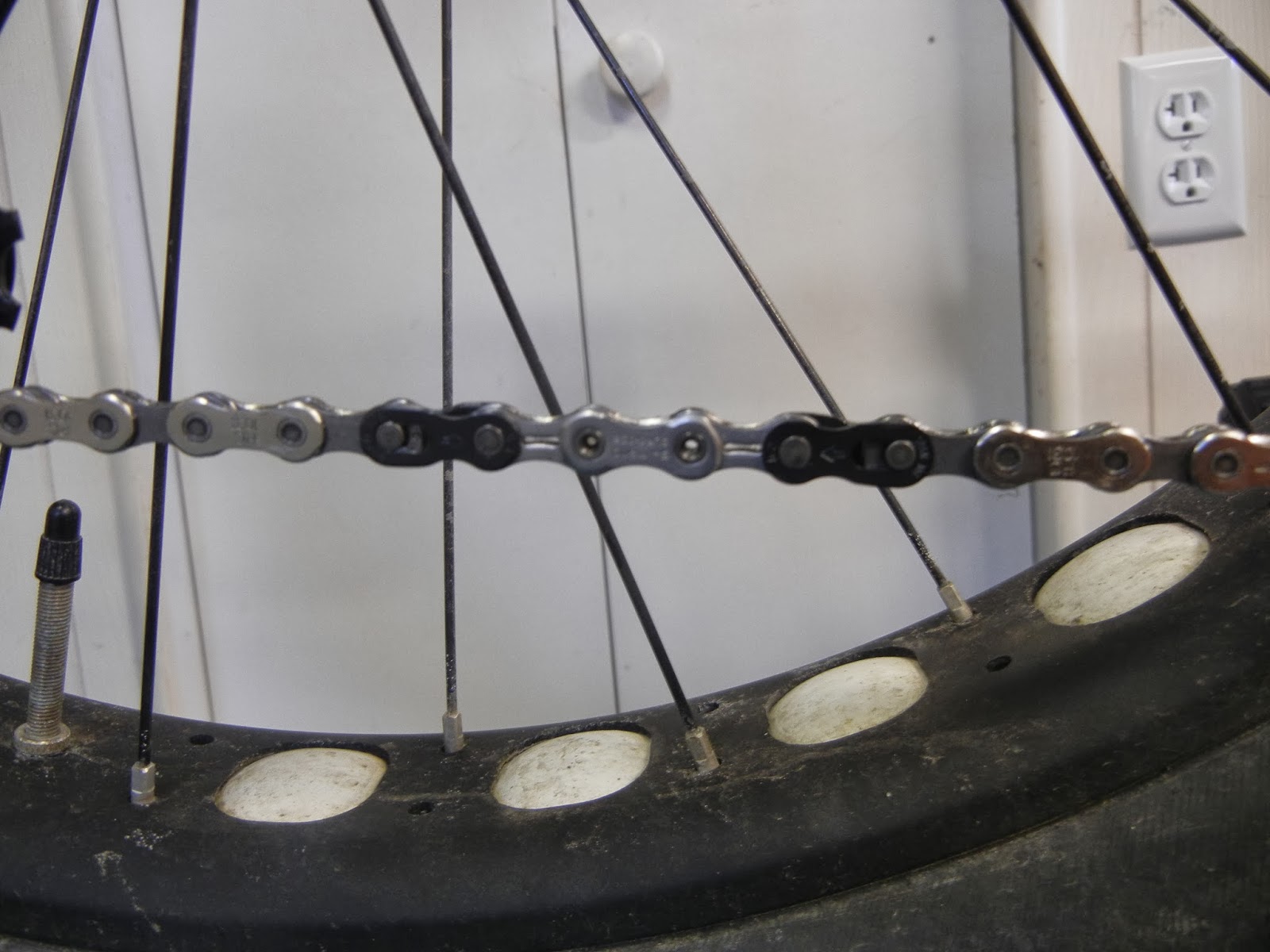 |
Uncut SRAM PC1031 114 link chain + extra master link and several spare links
 |
| Absolute longest chain the X9 medium cage can handle |
|
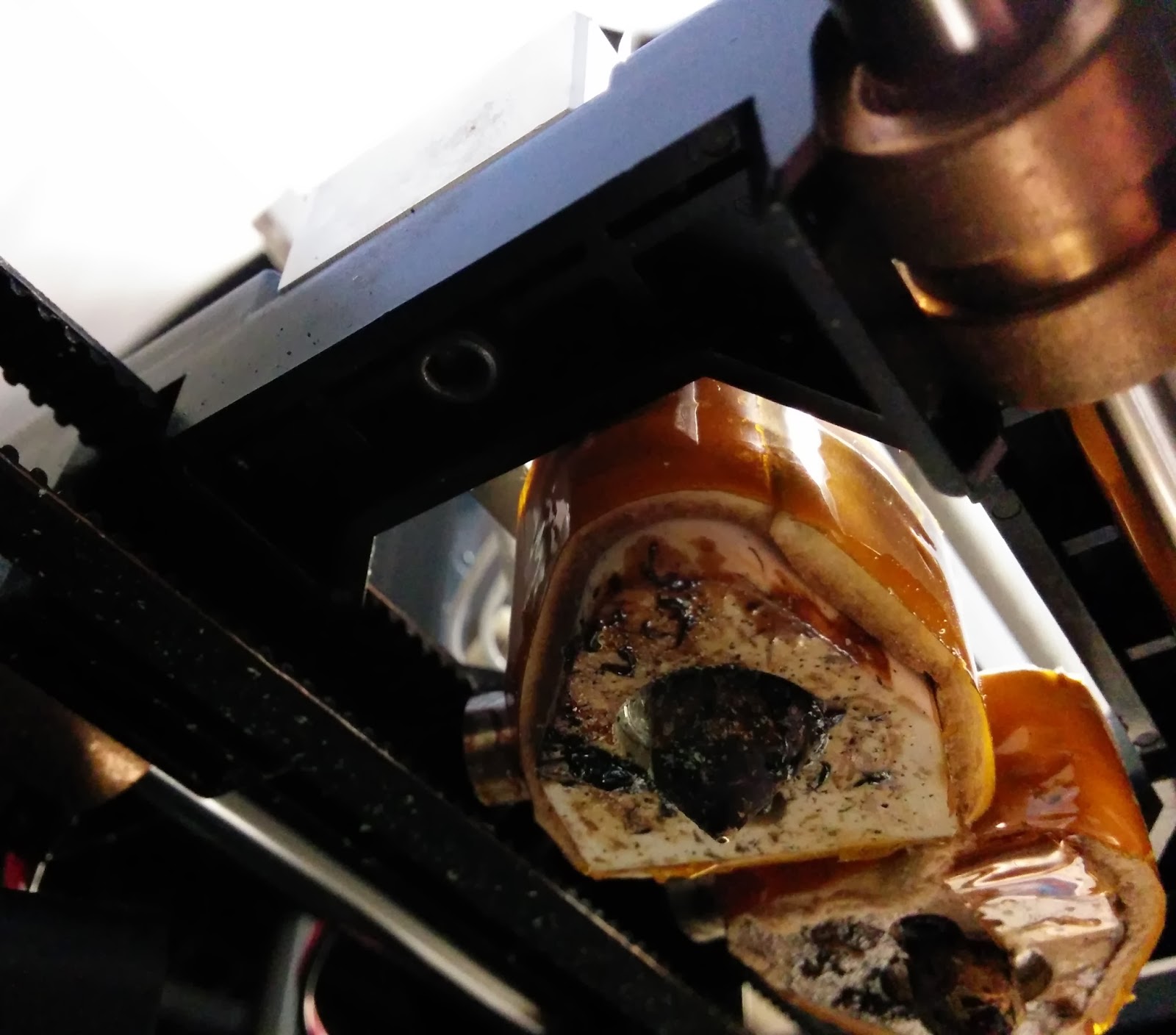
Once I had the chain length right, I could adjust the B-screw tension so the derailleur would shift into the 42T cog, as well as not rub while in the 42T. The trade-off in increasing the B screw tension is that the derailleur wraps tighter while in the 11T cog, causing the chain to rub together. (see photo below)
 |
| Slight contact between chain in 11T cog |
 |
| Tight fit, even with longer chain. X9 medium cage is maxed out |
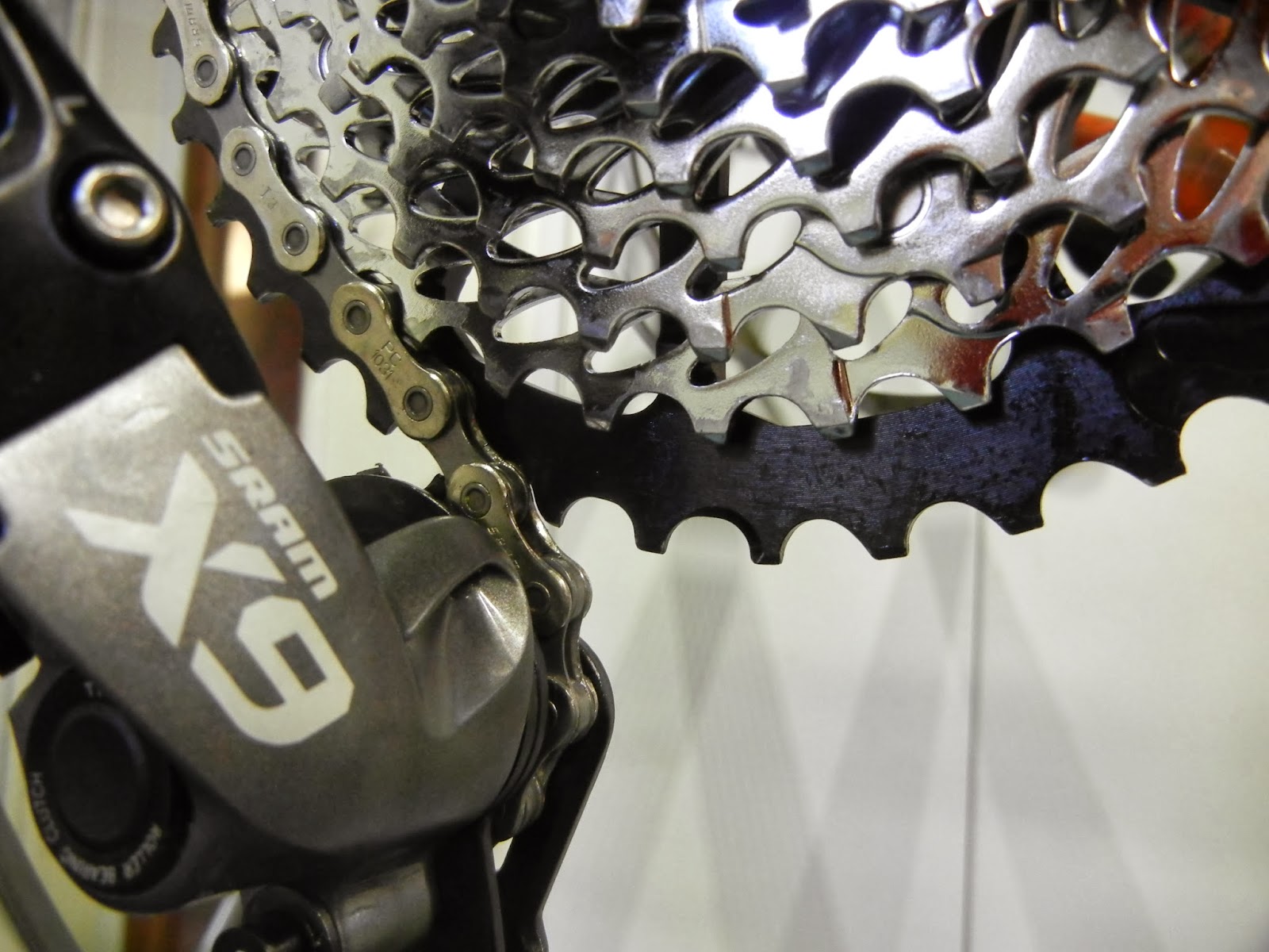 |
| Not quite right alignment when upshifting to the 42T- perhaps the 42T isn't seated on cassette |
Closing Thoughts
I thought the cog would install and tune easier than it did. I've never had to fine tune chain length, B-screw tension, and shift cable tension like this to get a system to work right. It still doesn't shift quite as nicely as I'd like into the 42T. From what Wolf Tooth says, though, it might change during the first ride when you put some torque into the pedals to shift the cogs into place. That might slightly improve the ramp / shift tooth alignment helping the shift. If that doesn't totally fix the hesitation going into the 42T I might take a file and remove a very small amount of material from the "shark tooth" teeth on the 42T that assist with shifting into the big cog. You can see in the photo above that the chain is slightly jamming against that "shark tooth" on the 42T cog and impeding the shift, so removing a tiny bit of material on that tooth face might help.
The verdict won't be in until the first ride though. I'm adding a lot of low end grunt with this upgrade- going from a 34T to a 42T is a big change! And, if it does work well (even marginally well going into the 42T) it should be a worthwhile upgrade- and much, much less expensive than upgrading to a SRAM X01 or X11 groupo.