Saturday, January 26, 2013

MendelMax 1.5 Build Log: Part 6, First Light!

Finally, I was able to get the MendelMax Reprap wired up and connected to a PC.

Steps along the way:

I went with 1/2" MDF to mount the heat bed

I drew a simple pattern- I wanted clearance for glass hold down clips, and the center cutout for the termistor


1/2" MDF Cut to shape

MDF Mounted to Y-Axis Slide
Zoom-in detail of  MDF mount on Y-Axis slide
The 1/2" MDF is attached to the Y-Slide using 4x M5 SHCS. The bed can be leveled by alternately tightening and loosening the screws. The way it's mounted it's rigidly affixed. I think as soon as I have the printer running I'm going to update it to add some spring mounts- so the bed can move if there is a head crash.

At this point I could do a very initial bed leveling by manually moving the X and Y axis to make sure the extruder head did not change height over the build plane. I did have to do some adjustments to the bed to get it as level as possible. I'll have to very carefully repeat this step once the machine is functional.

Next, I soldered the power connections and thermistor wires for the hot bed, and screwed it to the MDF.

RAMPS 1.4 board from Gadgets3D.com attached to frame using bracket off of Thingiverse.com


Everything Wired up Prior to tidying up the wires. Note the sweet cable chain on the Y axis also downloaded from Thingiverse (and printed on another printer) Once this printer is running I'll make similar cable chains for the X and Z axis.

Wires Cleaned up, Power Supply Attached (but not plugged in) and Arduino powered over USB

Gadgets3D.com LCD- showing no firmware yet loaded onto RAMPS / Arduino
After everything wired, cleaned up, and ready for first power- I gingerly plugged the USB cable from the Arduino to my old laptop. I didn't plug in the big 12V powersupply that provides the motivation for the steppers and heaters yet, I wanted to make sure all was well with the firmware first. No sparks or smoke- a good first sign.

I downloaded and installed the latest Arduino development environment, and installed the Arduino Mega 2560 drivers. Then, I downloaded the latest Marlin firmware from here.

I did an initial brush through the configuration file before I uploaded the firmware. Since I wasn't really sure of what initial settings are best, I used the recommended settings from the reprap mendelmax configuration page. I also used the modifications for the Gadgets3D LCD panel, described here.

After that, I saved, held my breath, and clicked on the compile/upload button. A minute or two later the LCD panel magically started showing a menu and current updates on the printer!


I downloaded what I've read to be the easiest to use printer interface- pronterface - from this location. I fired it up- and after I entered the correct COM port and Baud rate, it immediately recognized the RAMPS board. Bam. Then, I really held my breath and plugged in the big power supply. Amazingly, no sparks or smoke again. 2 for 2. I initially wanted just to test moving the various axis- unfortunately this is where I hit my first roadblock. I hit the button to manually drive the X axis, and immediately the error came up on both the LCD screen and the PC that the X endstop was hit, eventhough it clearly was not. I believe I need to re-examine how I wired all the endstops (NC or NO), plus whether or not I need a pull-up or pull-down resistor on each on. That'll be the story for another night. In the mean time it's exciting enough just to have it mechanically complete, preliminary wiring down, firmware onboard, and it being recognized by the host computer. Big progress!


Thursday, January 17, 2013

MendelMax 1.5 Build Log: Part 5, Endstop Switches

Before I dove into mounting the endstop switches on my rep rap Mendelmax 1.5, I took the opportunity to salvage a 12v fan and power supply plug out of a dead PC power supply scavenged from my office's technology junk pile.


The power socket on the left will make adding a plug to my 12V power supply neat. The fan will probably be used to either cool the RAMPS electronics or be used on the X-axis slide to cool down the extruded material.

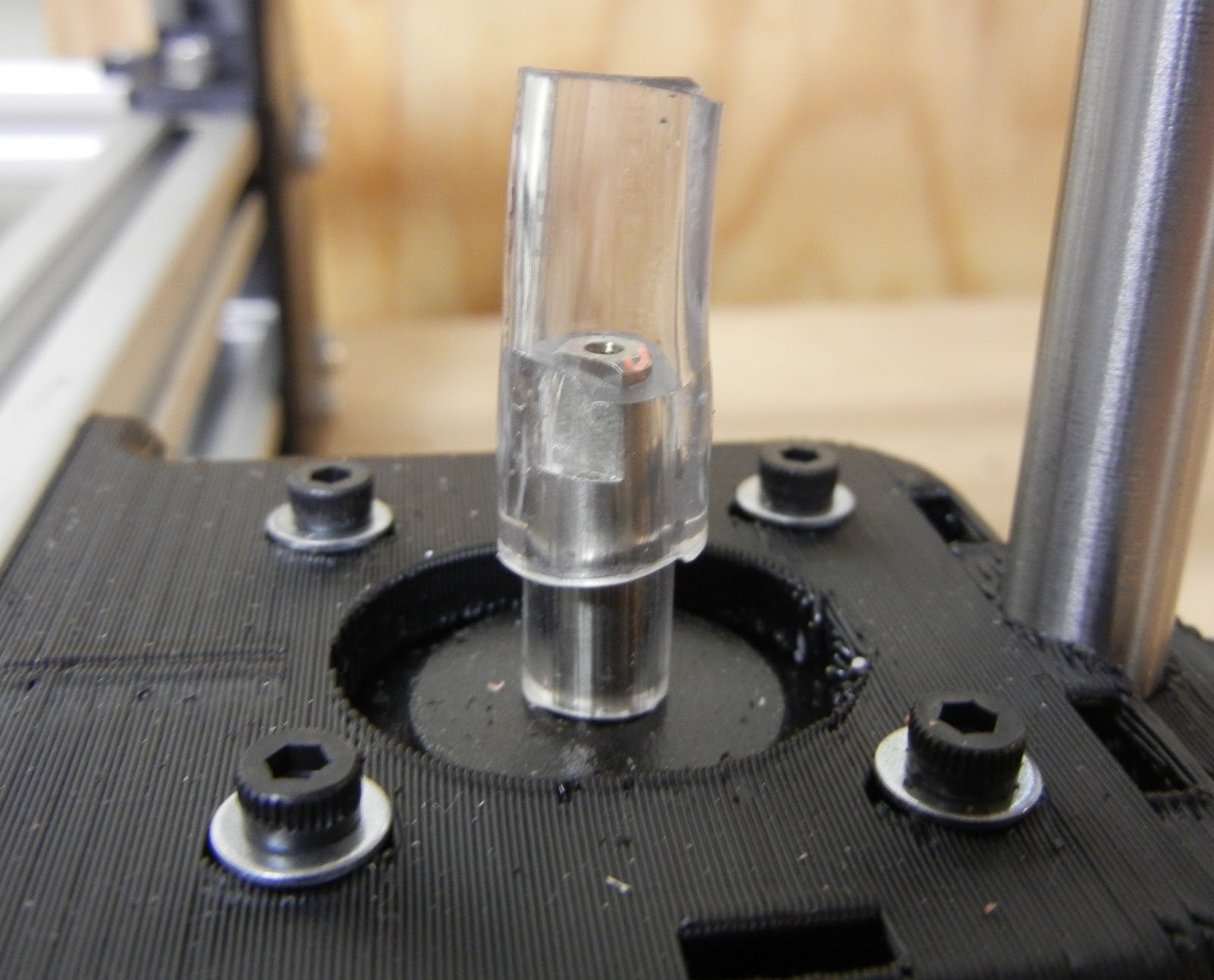
Next up was the mounting of the extruder to the X-axis slide. I didn't have the right M4 SHCS for the job, so I headed over to Lowe's. Being a standard hardware store, they didn't have a huge supply of metric hardware. But, they did have these M4 x 20 hex head screws, which actually worked perfectly.


M4 x 20 hex head screw inserted into the base of the extruder
Extruder and hot-end finally bolted to the X-axis slide!
Now it feels like I'm making some progress! The extruder and hot end are the heart and soul of the 3D printer. The RAMPS setup is the brain but I won't get into that in this post.

Lookin' good

Next on the list- mounting the endstop switches. Every 3D printer has at least 3 endstop switches. One for each axis- X, Y, and Z- and during startup, the machine moves each axis to zero by moving the components until the endstop is triggered. This calibrates the machine and could correct for any drift in the steppers or movement when the machine is turned off. The "stock" endstop mounts are a bit cheezy, and I wasn't able to find anything "just right" on Thingiverse. Luckily we now have a Afinia 3D printer at work, so I was able to design and print new Y and Z axis endstop mounts. I ended up using the stock X axis mount, at least for now.

First, the Z-axis. The X-end mount (in red in the photo below) already had holes in it for the Z-axis mechanical endstop switch. These holes were the right size for a set of 2/56 SHCSs. But, there was no good way to attach anything for the switch to act against. I also wanted this endstop to be easily adjustable- this stop is particularly critical because it will allow for precision adjustment of the extruder nozzle over the print bed.

Z-axis switch mounted
I noticed that the Z-axis motor mount support would be a great place to put a threaded hole- if it were only a bit wider. So I drew up a new bracket, printed it up on the Afinia, and vola. One adjustable mount perfectly positioned. I placed the files on Thingiverse.com if anyone is interested in doing the same.

New Z-axis motor mount with integral Z-axis stop

Z-axis endstop switch, actuated
Next, the Y-axis. I chose to build a framed-in Y-axis slide using Bosch 80/20 style aluminum extrusions. This was easy and made a very stiff and solid Y-axis slide. It also provided a great place to put a endstop.

Front Right corner of the Y-axis slide, showing 90 degree bracket to be used as adjustable Y-axis endstop
I designed and printed a switch bracket that put the switch in the right place. To finely adjust the endstop location, you can move either the switch bracket or the 90 degree bracket attached to the Y-axis slide, whichever is easier. The files for this part are also now on Thingiverse.

Y-Axis switch bracket

Y-Axis switch bracket

Y-Axis endstop switch and bracket installed

Y-axis bracket & switch installed, showing endstop activation

30,000 foot view of the completed Y-axis
The mechanical assembly of the 3D printer is basically complete.There is the matter of construction the build platform, but that should be pretty simple- just a sheet of MDF or plywood on top of the Y-axis slide, and a sheet of glass cut to size.

Now into the unknown- wiring, programming, and setup of the RAMPS controller. Maybe first movement this coming weekend?

Sunday, January 13, 2013

MendelMax 1.5 Build Log: Part 4, Y-Axis Carriage construction

The next step of my RepRap MendelMax 1.5 build was to construct the Y-axis carriage. I didn't purchase any of the pre-made Y-axis bearing plates. Since I had plenty of the Bosch aluminum extrusion left from my frame build, I built the Y-axis carriage from the scraps. I chose to make the Y-axis carriage 8" per side. This will give about 1/4" of overhang for the heated build platform. 

Frame built & screwed together using 90 degree brackets
Holes & counterbore drilled for corner build platform leveling screws (4x)
T-Slot nuts installed for Pillow Blocks (8x T-slot nuts) and Belt Clamps (4x T-Slot nuts) I put a piece of painter's tape over the end of each extrusion to prevent the T-Slot nuts from falling out when I was installing the Y-axis carriage.

Y-Carriage installed in Mendel Max 1.5 frame- showing detail of belt clamps and 8mm bushing pillow blocks
Y-Axis Carriage Installed!
Now the mechanical assembly is basically finished. I still have to install the extruder, hot end, and (3x) endstops.

The RAMPs 1.4 controller board, Arduino, and power supply also arrived at my doorstep last week. I'm a bit unsure of the installation, wiring, and setup of the electronics. It seems like most people on the web who are building these printers come from the software / electronics side of the world- so their tutorials are almost always fairly in depth for the mechanical assembly but gloss over the electrical side. I have completed a few arduino based electronics projects so I'm sure I'll be able to fumble through it.


Tuesday, January 8, 2013

Mendelmax 1.5 Build Log: Part 3: Flex Couplings

Tonight's activity was to build the flex couplers to link the Z-axis steppers with the acme threaded rod. Rather than purchase a machined flex coupler, or to use a printed coupler, lulzbot.com recommended using a home-made coupler. They recommended using a 5/16" OD x 3/16" ID tube and a 7/16" OD x 5/16" ID tube along with small pipe clamps.

Large Tubing
Small Tubing
Tubes cut to length
Initially I tried a 1.5" long large tube and 0.75" long small tube. I wasn't able to fully insert the small tube into the large tube, so I changed to 0.75" length for both tubes.

Constructed Coupler- about a 1/4" overlap
Coupler Attached to Stepper Shaft
Pipe Clamps Applied
Hot End- Not Quite a fit
X-Slide Trimmed- Hot End Inserted

Friday, January 4, 2013

MendelMax 1.5 Build Log: Part 2: X-Axis Build

The ACME lead screws and nuts showed up, along with the promised replacement parts from www.lulzbot.com.

Next steps in the rep rap Mendel Max 1.5 build- assemble the X-axis ends. I ordered the lulzbot ACME Pillow Block X-End Set 2.0. The Z-axis rods are 10mm, and the X-axis rods are 8mm.
ACME nut in the bottom half of one of the X-ends

The ACME nut didn't quite fit- trimming the socket with a X-acto knife

Perfect Fit!
Lulzbot.com was out of the extruder components, so I decided to order some from an e-bay seller. I found a seller located in Hutchenson, MN who was selling parts at a very reasonable price. I also purchased some printed endstop switch brackets, "pillow blocks", and belt clamps as well.

Additional Parts from E-Bay seller
The SDP bushings for the 8mm and 10mm rods both have the same OD, so the printed "pillow blocks" are the same for all size bushings. The printed "pillow blocks" were a bit rough on the inside, and the SDP bushings didn't fit with a reasonable amount of force. I learned my lesson on the X-carriage not to force the bushings. A round file worked great to clean out the inside of the "Pillow Block". With a little filing, the bushings pressed in place easily.

Filing Pillow Blocks

Pushing Pressed into Pillow Block

Assembled X-Axis assembly
X-Assembly in place
X-Axis in place with frame assembled
 With the X-axis assembly in place, I could start dialing in the mechanism. Unfortunately the Z-axis (vertical) wouldn't slide at all, it would easily lock up. Obviously something wasn't aligned right.

The right side of the Z-axis slide seemed to be tighter than the left. I removed one of the pillow blocks, and the assembly seemed to slide slightly easier.


One Pillow Block Removed
After inspection, it seemed the upper pillow block wasn't aligned fore and aft with the Z-axis slide. 

Adjusting Mounting hole with dremel.
Even after re-assembly the Z-axis still didn't slide right. After looking at the X-ends further, I saw that there were actually two additional Pillow Block mounting holes on the lower X-end.

See lower mounting holes on lower X-end

Pillow Block moved to lower X-end holes
The X-assembly slid much better up and down the Z-axis after moving the Pillow Blocks.

Lulzbot.com also sent the replacement lower vertices to replace the missing units from the original kit.

Replacement kit from Lulzbot.com
When I re-assembled the frame, I also took the opportunity to replace the upper cross braces with some heavy duty 8020 aluminum brackets from D&S Machined Products. The aluminum braces really stiffened up the assembly. As is, both the X and Z axis easily slide without binding.

Current State of MendelMax Frame

Current State of MendelMax Frame
Next steps:
  • Install Z-axis ACME lead screws
  • Assemble & install extruder & hot end
  • Build Y-axis sled & build platform