Thursday, August 9, 2012

DIY Solder Fume Extractor

I was tired of breathing in solder fumes- especially when soldering lots, and lots of connections for the various multi-rotors I've been working on. I didn't want to pay the $50 or whatever ready made fume extractors have been selling for, so I repurposed a 12v computer fan, 12v wall-wart and a new-work steel duplex box I had laying around.

I tried using some carbon foam filter left over from an old window AC unit, but it restricted the airflow too much. I mostly just wanted to suck the solder fumes down and away from my face when I'm soldering, so even without a filter it works great for this purpose. The computer fan is also very nice- almost totally silent and moves plenty of air. 

New-Work Square Steel Box in vise- tracing out zone to cut out with a sharpie

Sharpie marks the circle to cut out of box

Cutting with a metal cutoff saw in the dremel

Finished Rough Cut

Circle Trimmed Out, be sure to file down all the sharp edges!

The Size M DC power jack is for a left-over 12v "wall wart", and a SPST switch to turn it on and off

Box clamped in vice, holes drilled for the power jack and on/off switch

Components trial fit in box

Primed box

Box painted, Components installed & soldered in place

Ready for use!

Turnigy Micro Integrated PCB Quad Kit Build

The Turnigy Micro-Quad was a bit of an impulse buy- I saw pictures of it sitting in the palm of someone's hand and couldn't resist. Part of the cool factor is that the structure forms the power distribution board- it has a built-in PCB that you directly solder the ESC's and motors to. Hobbyking was perpetually out of the small brushless motor they recommended, so I chose a Hextronic motor that had similar specs. It turned out to work very well for this application.

Part QTY
Turnigy Integrated PCB Quad Kit 1
Turnigy Plush 6A ESC 4
Hextronic 2300kv 20g brushless motor 4
5x3 quad Propeller set, Black 1
5x3 quad Propeller set, Red 1
Turnigy nano-tech 850mah 2S 25~40C Lipo Pack 1
generic Spektrum DSM2 receiver 1

I cut the input and output leads down to about 1/8" longer than the heat shrink ESC package and stripped off as much of the insulation as I could. Before clamping the ESC to the quad's frame I dip coated each wire tip in flux.

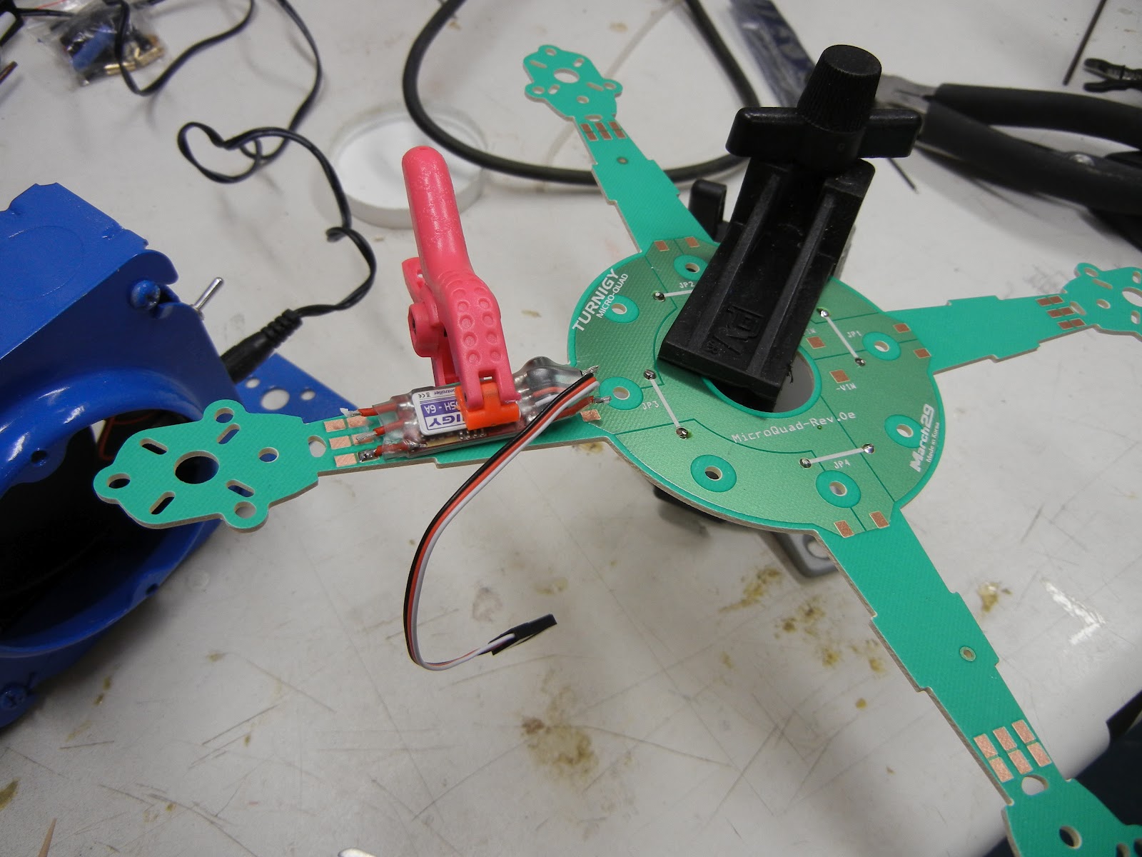
Micro-Quad frame clamped in PanaVise for easy access.

I used a heat-sink clamp to hold the wires in place during soldering. One down and two to go in this photo.
Once the ESC's were soldered in place I installed the motors. I used 2-56 x 1/4" SHCSs. I used a drop of CA on each 2-56 nut along with some CA kicker to act as a thread locker to prevent the nuts from vibrating off during flight.

Testing motor rotation direction using alligator clips
One slightly more tricky part of this build is that you had to get the motor rotation correct before soldering the motor leads in place, since there are not removable connectors between the motor and ESC. So, I soldered one lead in place, then used alligator clips to test a "guessed" motor hookup. I checked the motor rotation direction by hooking up the receiver and throttling up. If it was correct I soldered the leads in place. If not, just rotate the leads, test again, and solder when correct.


Soldering motor leads in place- note ball of flux on the motor lead wire tip
Once all of the motors and ESCs were soldered into place, I glued together the structure with medium viscosity CA.

Turnigy Talon V2: Part 6, Improved Electronics Mounting

Next, I decided to improve the mounting method for the receiver and make room for a Spektrum TM1000 telemetry unit. Telemetry is a great thing to have with an electric aircraft- you can keep an eye on battery voltage to make the best use of your flight time. In order for the TM1000 to transmit your flight pack voltage level, you need to tap the battery somewhere upstream of your ESC's or other electronics. The Hobbyking Quadrotor power distribution board has a nice voltage tap that works great for this purpose. I used a servo lead off of a fried servo for a connector. I pulled off of the signal line to leave just the black and red wires on the servo cable. A JST connector would probably work as well.

quadrotor power board TM1000 voltage tap hookup
To fit the extra TM1000 (and remote receiver) I chose to extend the mounting screws. I couldn't find any 4/40 screws longer than 1.5", so I purchased some 4/40 x 3" threaded rod.

Talon V2 top plate with threaded rod installed

Power Distribution Board and Flight Control Board installed. Note rubber grommets above and below FC board

Receivers and TM1000 velcro'd to plastic cut into squares (from food packaging) ziptied to threaded rods

Top view of Receiver, TM1000 Mounting

Installed on the Talon V2

Mess 'o' wires!

I wasn't happy with the home made aluminum landing gear, switched back to the 600 heli landing gear.