I again used a dremel cutter to remove foam for the two battery locations. The 1050 mAh battery location only extended 1/2 way through the center wing section. The 2150 / 2200 mAh battery location, on the other hand, requires a full depth removal of foam. I'll have to create a "floor" for the battery compartment with lite-ply or 1/4" foam. The dremel works, but it is messy and time consuming. I think I'll be building or obtaining a small hot wire cutter to make future foam cuts.
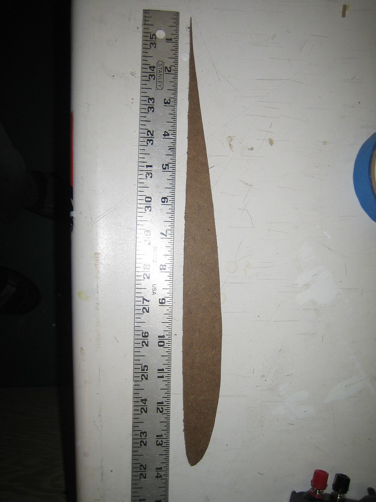
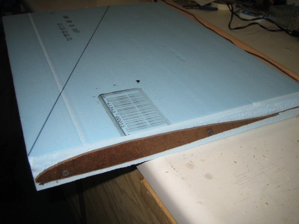
After cutting the battery compartment holes it was very obvious the wing needed some sort of wing spar. I was hoping the prototype wouldn't need them, but after the cuts the wing had very low flexural rigidity. I chose to use some 1/8" x 1/2" scrap to fashion spars rather than carbon. I'll save the expensive carbon for the real high speed machine.
I used my soldering iron to cut the spar channels rather than the dremel. This worked, but the slots were a little too wide. I would have preferred tight-fitting channels. To fill the gap, rather than heavy epoxy or hot-glue I used white Gorilla Glue. I soaked the spars in water, wiped the excess off with a towel, then set them in the channels. I tried three techniques to apply the glue, one for each spar section:
Apply gorilla glue to each side of the spar, then insert in the channel
Place spar in channel, squirt glue on each side of spar
Squirt glue into channel first, then place spar.
After the glue is cured it should be obvious which technique is best and will be used for future aircraft.
Once the spars were in place I put a stripe of "extreme" 3M packing tape over the top, to keep the Gorilla glue in place and to add additional strength.
A word about buying batteries from www.hobbyking.com: high quality batteries, low price- but it's a lotto pick on which connector you get on your batteries. For some reason on my last order I received two batteries with EC3 connectors, and two batteries with a "mystery" connector. Hobbyking, if you are out there- just ship your batteries with bare wires. Soldering new EC3 connectors on is pretty easy.Horizon Hobby has an excellent video on their Youtube channel.
Tonight I covered the elevons with 3M "Extreme" packing tape. The elevons went from being super floppy- basically no torsional rigidity at all- to being reasonably stiff. At least I think they'll be stiff enough to work. I attached the elevons with 3M Blenderm tape. When I connected the servos to the surfaces using some old control horns from an old gas model, I cut the horns down to use the most aggressive hole. After I did this I realized the disadvantage- this hole not only gives the most surface travel vs. servo travel, it also gives the most slop. I'll have to watch this when I build the 'real' speedwing.
I tested the surfaces, and verified they were moving in the right directions. The elevator / aileron mixing seems to work well. This model should have plenty of control authority!
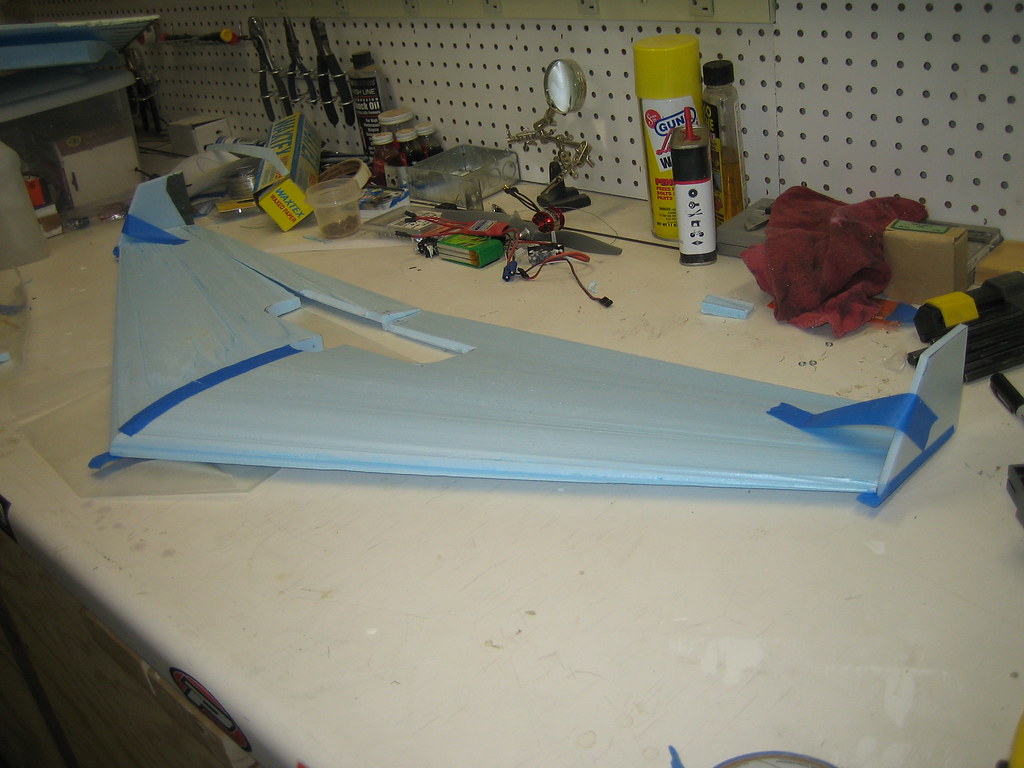
After using a dremel to core out space for the ESC, receiver, and various hook-up wires it was time to verify the CG is still ahead of the neutral point. I tried balancing the wing using a 2200 3s, a 1050 3s, and a 2150 4s. All appear to work assuming that the battery has to fit within the boundaries of the wing. Note the batteries are all pictured in approximately the location required to have the CG just ahead of the neutral point (NP).
Finally, I attached a 9x6 APC E prop to try out the motor. Even with the 3s battery it seems to have a much greater than 1:1 thrust to weight ratio. Provided the wing is controllable it should be a blast to fly! With the smaller batteries it should also be a good floater.
I'm rethinking my initial plan of not adding any spars or reinforcement except for external packing tape. After I core out enough material for the various battery options there isn't going to be much left at the wing root. I haven't yet decided if I'll add simple carbon spars, or else cut some plywood spars to join the two wing cores across the battery cavity.
It outlines a pretty easy process for finding your neutral point and center of gravity for both straight (plank) flying wings and swept / tapered wings.
I used the formula and method for the swept / tapered wing. From the listed formulas to find the mean chord length and location of mean chord length, you simply draw a perpendicular line back from the chord/4 length from the leading edge at the mean chord loction back to the wing root. This locates your neutral point. (NP) The CG should be placed just ahead of the NP location.
My results for the 40" wing:
Mean Chord: 9.44" C/4=2.4"
Mean Chord Location: 8.38" from wing root
Then, graphically solving on the wing, the NP is 6.75" back from the leading edge.
I did a rough finish sanding using 100 grit sandpaper glued to a scrap block of foam. This worked great- yielded a nice smooth finish without ripping the foam. The foam didn't load up the sandpaper either. I used Elmer's glue to attach the sandpaper.
I only took the high spots off of the wing- I'm not going to try and remove all of the spanwise artifacts from the wire cutting process. I'm afraid I'll remove too much of the airfoil. I also made sure the leading edge was nice and rounded.
The prototype wing is coming together well. Last night's activities:
Trimmed trailing edge of wing to square it up and bring it to a uniform thickness
Cut out elevons and prop hole
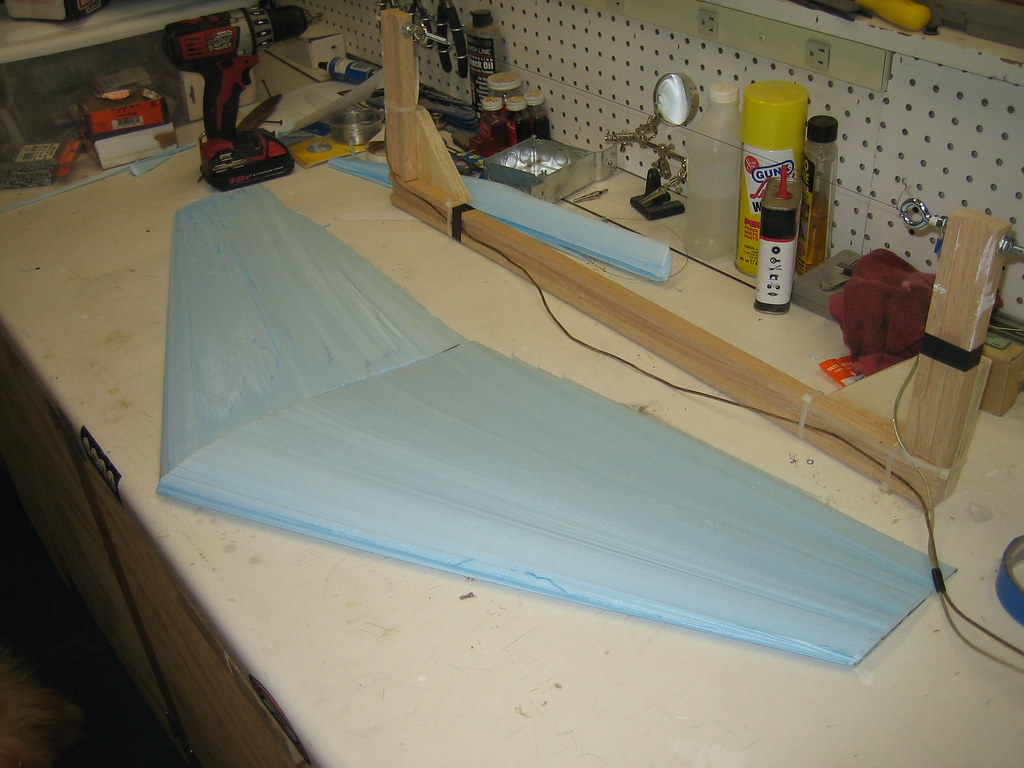
Mitre cut wing root to add 0.5" of dihedral
Glued wing halves together (using 5 minute epoxy)
Attached winglets (using 5 minute epoxy)
I've deviated from the original design. This prototype is going to be built up as a lightweight floater, just to test the wing geometry, construction techniques, etc before I put together the final high speed wing. The elevon size, motor location and winglets were all eyeballed- no calculations used. This may prove a mistake, but it will be interesting to see how it flies. Since it is so lightweight it should be durable enough to try several different thrust angles and motor offsets. I also extended the elevons behind the prop to give some measure of vectored thrust to try and improve extreme slow speed maneuverability.
The resulting glued up fusalage is darn lightweight- only 95.6 grams.
So far, looks good. The Esky 1000mAh batteries I have are total junk, so I'll try to fly this with the 500mAh 3 cells or 800mAh 2 cell batteries until the Rhino 1000mAh's arrive. I may also cut out the wing enough to allow trying the 2200mAh 3cells.
The next steps are to find some of the fancy 3M double reinforced packing tape for "spar" reinforcement and wrapping the elevons, plus some colored packing tape to cover the wing. I may also insert some balsa into the elevons behind the prop to stiffen them up.
Top view, components arranged before cutting elevons or gluing wing cores together
Dry fit components, including pilot
Components epoxied together & drying (notice sweet painter's tape clamps)
Based on an estimated foam density of 2.2 pounds / cubic foot, Solidworks estimated the foam cores would weigh 3.81 pounds. (this is the raw cores before cutting the lightening holes, prop cutout or area for electronics.)
After cutting the cores, I weighted them with a precision scale: 97.1g = .21 pounds
This is way off from the estimated weight! Assuming the real parts have the same volume as the Solidworks model, using this value to back-calculate the density of the foam, the actual foam density is 1.48 pounds / cubic foot. So, for anyone using the Blucore foam (sourced at my local Lowe's)- you may want to use value. I'd also recommend checking for yourself what your foam density is to account for mfg. variability.
I adjusted the inputs to Solidworks, and the new total all-up flying wing weight is 1.3 pounds. Besides making the aircraft lighter, it also has the welcome effect of moving the CG forward- it is now in the desired CG zone. (based on the Ritewing Demon CG location)
I also ordered Model Aircraft Aerodynamics. I'm going to do some more thourough calculations to locate the center of lift, thrust angle, etc.
In the mean time, I'm planning on doing a "quick and dirty" build up with the initial wing cores to do a rough feasibility flight test to make sure I'm on the right track.
Tom helped me out last night with the maiden run of the hot wire cutter. It worked pretty well, and I now have a set of wing cores to try out. However, the surface finish isn't as good as I'd like. I'm going to modify the cutter fixture to try and improve the finish. The flying wing design is a challenging first wire cut wing, since the root and tip of the wing have very different chord lengths, as well as having a substantial sweep.
Wire Cutter Modifications:
Remove tension spring, only use eyebolts to add tension. This will allow a higher wire tension as well as increase the "throat" of the tool.
Build a fixture to hold the workpiece to the work bench.
Build a fixture to control the motion of the wire cutter
John and I are competing in an unofficial "top speed" construction contest. Only rules are that the aircraft needs to be electric powered, and must be flying after the top speed attempt. The contest will take place on March 1st 2010, at a place to be determined.
I am designing and building my own entry. So far my chosen configuration is a flying wing with dimensions modeled after the Ritewing Demon 40, with a HS522 airfoil. My initial design had a 40" wingspan. I'm thinking that I will build the 40, but perhaps with a better low speed airfoil, and use the first airplane for a test bed. I'll probably use a lower powered drive system for the initial build.
I selected the HS522 airfoil based on data found on this german (english language) website: http://www.aerodesign.de/english/profile/profile_s.htm http://www.aerodesign.de/english/profile/profile_s.htm
Translating Airfoil section co-ordinates to Solidworks Model: This is fairly easy to do, but takes a few steps: 1) copy x,y coordinates from source website.
2) paste into text file. If you try to directly paste into excel, you'll lose the data columns. Save the text file.
3) Import into excel. The data is delimited with spaces, it should be a straightforward import process. 4) remove column headers. Add a third "z-axis" column- also without a column header. Fill this column with all "0", since you want the airfoil cross section to be in the same datum plane. Save first as excel file. Then, save as a txt file. Only save this workbook sheet.
5) Open Solidworks. Create a new part file. Insert a "curve through XYZ points". Click on "browse", select your text file. Once the curve is selected, you'll have create a new sketch, select the 3D curve you created, click on the curve, copy the curve into the sketch, then scale the curve to the size you need for your design.
Phew!
Initial "Speedwing" Power System:
Turnigy 2836 3200kv motor
Rhino 2150 mAh 4s pack
Turnigy Plush 80A speed control
6x4 Prop
This system yields a maximum pitch speed of 179 mph
I've been modeling the aircraft in Solidworks, and trying to keep the calculated CG within the recommended location for the Ritewing Demon. I've been having a hard time keeping it far enough forward, so I've cut lightening holes in the wing and vertical stabilizers.
Density Assumptions: (all from web searches)
Bluecore foam density: 2.2 lb/ft^3 - NOTE: I discovered this density isn't accurate, see later post for measured value
Balsa density: 10 lb/ft^3
Carbon fiber density: 115 lb/ft^3
Next I'm going to try and calculate the center of lift for the wing and make sure it matches up with the recommended CG location from the reference Ritewing Demon design.